
VGT(Variable Geometric Turbocharger) is the device which increases the efficiency of turbocharger at low rpm and lasts optimum turbo efficiency at high rpm as varying the cross sectional area through which exhaust gas passes turbocharger impeller. It relieves turbo lag at low speed and increase engine power generation.
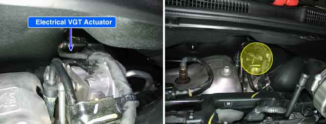
The electronic VGT adapted on S engine is activated by VGT actuator control unit and electronic actuator integrated with DC motor. Engine speed, APS signal, MAFS and Boost pressure sensor data are inputted to ECM. ECM controls VGT actuator control unit to control exhaust gas line as controlling VGT actuator duty to maintain optimum state of air compression. VGT actuator control unit controls DC motor with those signal so that exhaust gas can pass through the vane more or less cross sectional with operating spear gear→outter crank→ inner crank→main link→ unison ring→inner vane in order.
VGT actuator control unit judges that actuator is faulty by feed back signal of actuator position from turbo charger position sensor. If it is detected, VGT actuator control unit notifies faulty to ECM. The electronic actuator is much faster in operating response and stable in control than vacuum type.
In case of replacing E-VGT, perform the "COMPONENT CHANGE ROUTINE" procedure with scan tool. If the "COMPONENT CHANGE ROUTINE" procedure has not completed until automatic learning completed, it may cause vehicle performance and exhaust gas problem.
The ECM set DTC P2263 if excessive difference between modeled and actual value of VGT has been detected for 25 sec. This code may result from malfunction of VGT actuator, overload, or error in teaching procedure.
Item | Detecting Condition | Possible Cause | ||
DTC Strategy |
•
Signal Monitoring |
•
Overload.
•
Error related VGT actuator learning.
•
Faulty VGT actuator. | ||
Enable Conditions |
•
Engine Running | |||
Threshold Value |
•
Faulty following target value
•
Overload.
•
Error related learning. | |||
Diagnostic Time |
•
25 sec. | |||
Fail Safe | Fuel cut | NO |
•
- | |
EGR Off | YES | |||
Fuel Limit | NO | |||
Check Lamp | OFF | |||
Fig.1) VGT operating signal and Feed-back signal at idle.
Fig.2) VGT operating signal and Feed-back signal at 4000RPM.