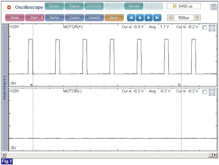
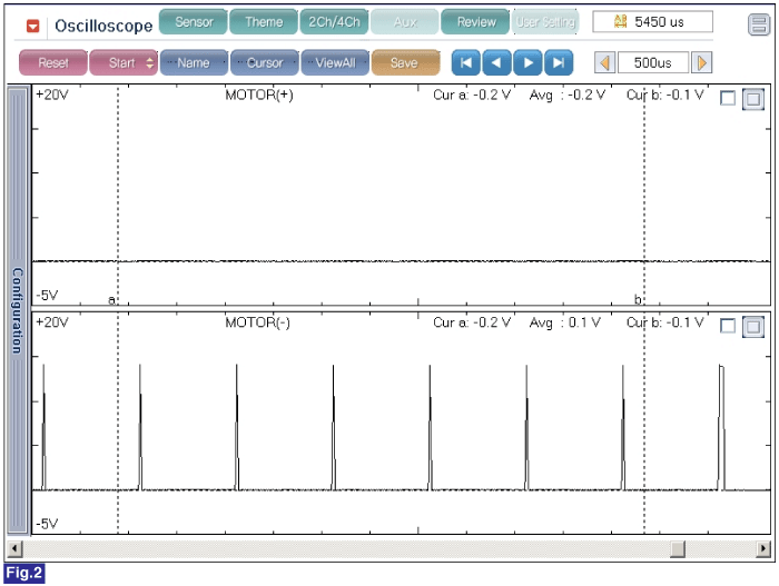
Monitor the signal waveform at idle and during acceleration.


Fig.1) Signal waveform when variable swirl valve closed at idle.
Fig.2) Signal waveform when variable swirl valve opened at acceleration.
IG key OFF.
Disconnect VSCA connector.
Check resistance between 'Motor (+)' terminal and 'Motor (-)' terminal of VSCA connector. (VSCA component side)
Specification : 3.43 Ω ~ 4.37 Ω (20℃)
Connect VSCA connector.
Connect one prove of oscilloscope to 'Motor (+)' terminal of VSCA connector. (VSCA component side)
Connect another prove of oscilloscope to 'Motor (-)' terminal of VSCA connector. (VSCA component side)
Engine ON.
Monitor the signal waveform at idle and during acceleration.


Fig.1) Signal waveform when variable swirl valve closed at idle.
Fig.2) Signal waveform when variable swirl valve opened at acceleration.
Is the measured value within specification and is the signal waveform normal?
 | ▶ Go to "Verification of Vehicle Repair" procedure. |
 | ▶ Replaces VSCA, and go to "Verification of Vehicle Repair" procedure. |
In case of replacing VSCA , perform the "COMPONENT CHANGE ROUTINE" procedure with scan tool. If the "COMPONENT CHANGE ROUTINE" procedure has not completed until automatic learning completed, it may cause vehicle performance and exhaust gas problem.