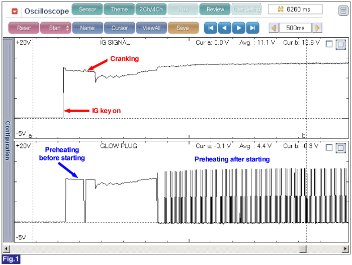
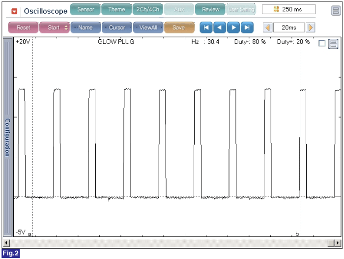
IG key ON, and monitor the signal waveform at 'GLOW PLUG #' terminal of 'GLOW PLUG #' harness connector.(Or connect GDS with 'DATA LINK CONNECTOR'(DLC) and perform actuation test -"GLOW RELAY" with GDS.)


Fig.1) Signal waveform of glow plug before and after starting at 30℃ engine coolant temperature with IG key operation.(IG key OFF to Cranking)
Fig. 2) Signal waveform of glow plug at Idle status.
☞ 1~ 2sec. after IG key ON, operating duty for glow plug reaches approx. 100%. After that, PWM is controlled corresponding engine condition.(Approx. 30 ~ 32Hz)


