Component Location
General Description

The ratio monitoring controls the nominal gear box ratio to the real gear box ratio. While driving in a gear(reverse, first second, third…) there is a calibrated rationality check between turbine speed and output speed of the corresponding gear.While up or down shifting from one gear to another there is a calibrated rationality check between turbine speed and output speed of the corresponding shift. While engaging the gear there is a calibrated rationality check between turbine speed and output speed of the corresponding shift if the actual output speed is higher or equal than a calibrated threshold.

While engaging the gear when the actual output speed is lower than the threshold there is a rationality check on the turbine speed.

DTC Description

TCM set this code if the value of input speed(turbine speed) is not equal to the value of the output speed, when multiplied by the 1st gear ratio, while the transaxle is engaged in 1st gear. If this code outputted, Check the Engine system first and then follow this procedure.(MIL ON : 2 driving Cycle)

DTC Detecting Condition

Item

Detecting Condition

Possible Cause

DTC Strategy

Gear ratio monitoring

Check the Engine system and DTC

Mechatronics(E-module + Valvebody) => Solenoid valve"1"&4"

Replace ATM

Enable Conditions

CASE1

Output speed ≤ 50 rmp

CASE2

1st gear shifting with 0.5 second

Output speed ≤ 50 rmp

Threshold Value

CASE1

Actual engaging gear ratio ≥ target gear ratio

Actual engaging gear ratio < target gear ratio

CASE2

Input speed when start to monitoring - actual Input speed < 40 rpm or

Input speed when start to monitoring - actual Input speed ≥ 40 rpm

Diagnostic Time

3times function check

Fail Safe

No learning control

Fixed at 3rd gear

(priority : 3)

caution
1.

The function with the higher priority will aiways take precedence. However, a low-priority is not overruled by a higher priority function.

2.

Functions from different priority categories can also run in parallel. It is important to note which function will take precedence in this case.

3.

In such an event it is possible for a substitute function with low priority not be carried out if a second, higher-priority function is present. This has been taken into account when compiling the priority list and is international.

4.

The mechanical emergency run function must always have the highest priority, since from the electrical standpoint it is the only safe condition.

Signal Waveform & Data
Solenoid valve operating status according to gear position

gear

position

ON SOL.

SOL.1

SOL.2

SOL.3

SOL. 4

SOL. 5

SOL. 6

P

OFF

48mA

848mA

48mA

48mA

-O-

OFF

R

OFF

48mA

48mA

48mA

48mA

-O-

OFF

N

OFF

48mA

848mA

48mA

48mA

-O-

OFF

D1

OFF

848mA

848mA

48mA

48mA

-O-

-O-

D2

OFF

848mA

848mA

848mA

848mA

-O-

-O-

D3

OFF

848mA

48mA

48mA

848mA

-O-

-O-

D4

ON

848mA

848mA

48mA

48mA

-O-

-O-

D5

ON

48mA

48mA

48mA

48mA

-O-

-O-

D6

ON

48mA

848mA

848mA

48mA

-O-

-O-

-O- : variable control

Fig 1) Solenoid valves in 6th gear

Fig 2) Solenoid valves in 6th gear-graph

Fig 3) Solenoid operating status - D1 gear to D6 gear

Monitor Scantool Data
1.

Connect scan tool to data link connector(DLC), Ignition "ON"

2.

Erase DTC and Engine "ON"

3.

Monitor the "Current Gear, Target Gear, solenoid valves" parameter on the scan tool.

4.

Select "D" range and Drive vehicle, confirm output data of solenoid valves.

Solenoid valve operating status according to gear position

gear

position

ON SOL.

SOL.1

SOL.2

SOL.3

SOL. 4

SOL. 5

SOL. 6

P

OFF

48mA

848mA

48mA

48mA

-O-

OFF

R

OFF

48mA

48mA

48mA

48mA

-O-

OFF

N

OFF

48mA

848mA

48mA

48mA

-O-

OFF

D1

OFF

848mA

848mA

48mA

48mA

-O-

-O-

D2

OFF

848mA

848mA

848mA

848mA

-O-

-O-

D3

OFF

848mA

48mA

48mA

848mA

-O-

-O-

D4

ON

848mA

848mA

48mA

48mA

-O-

-O-

D5

ON

48mA

48mA

48mA

48mA

-O-

-O-

D6

ON

48mA

848mA

848mA

48mA

-O-

-O-

-O- : variable control

Fig 1) Solenoid valves in 6th gear

Fig 2) Solenoid valves in 6th gear-graph

Fig 3) Solenoid operating status - D1 gear to D6 gear

5.

Does solenoid valves "3" & "4" operated normally ?

▶ Fault is intermittent caused by poor contact in the sensor's and/or PCM/TCM's connector or was repaired and PCM/TCM memory was not cleared. Throughly check connectors for looseness, poor connection, bending, corrosion, contamination, deterioration or damage.Repair or replace as necessary and go to "verification of vehicle repair" procedure

▶ Go to "Component Inspection" procedure

Component Inspection
1.

Ignition "ON" & Engine "OFF".

2.

Connect scantool and check DTC.

3.

Erase the DTC with scantool.

4.

After turning IG OFF to IG ON twice or three times, check DTC again.

5.

Does the scantool show same DTC again ?

▶ Substitute with a known-good Mechatronics (Valve-body + TCM) and check for proper operation. If the problem is corrected,replace Mechatronics (Valve-body + TCM) and then go to "Verification of Vehicle Repair" procedure.

▶ In case of Automatic Transaxle problem(clutchs, brakes), Check the oil level.

If oil level is normal, replace Automatic Transaxle and Go to "Verification Vehicle Repair" procedure.

▶ Fault is intermittent caused by poor contact in the sensor’s and/or PCM’s connector or was repaired and PCM memory was not cleared. Thoroughly check connectors for looseness, poor connection, ending, corrosion, contamination, deterioration, or damage. Repair or replace as necessary and go to "Verification of Vehicle Repair" procedure.

How to perform Initial Learning

If you replace the automatic transmission or Mechatronics (Valve-body + TCM), or if you overwrite the TCU software, be sure to initialize the learned values and perform initial learning.

Step 1) Warm-up

Raise the ATF temperature by leaving the vehicle idling or performing city drive. Check the ATF temperature using the Scan-tool and make sure it is between 50°C( 122 °F) and 120°C( 248 °F). If the ATF temperature is outside this range, work to bring the range.

caution

Don't raise the oil temperature by stalling the engine.

(Reference)

If the oil temperature is not between 50°C( 122 °F) and 120°C ( 248 °F), initial learning can not be performed. Before learning, check for variable speed shock or shift shock.

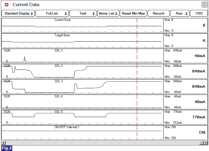
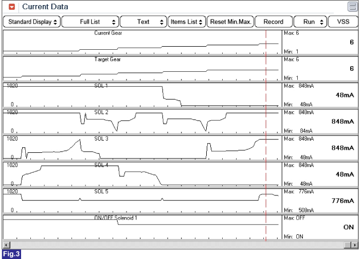
STEP 2) Driving learning

Select "D" range then depress accelerator pedal smoothly, and keep the APS value 17%, shift gear to 5th gear.

RKeep the vehicle speed over 60kM/h.

In condition that release the accelerator pedal and then depress the brake pedal narmally.Stop the vehicle then keep 5seconds.

STEP 3) Repeat this procedure 10 times.(Not necessary N-D,N-R Learning)

Verification of Vehicle Repair

After a repair, it is essential to verify that the fault has been corrected.

1.

Connect scantool and select "Diagnostic Trouble Codes(DTCs)" mode.

2.

Using a scan tool, Clear DTC.

3.

Operate the vehicle within DTC Enable conditions in General information.

4.

Are any DTCs present ?

▶ Go to the applicable troubleshooting procedure.

▶ System performing to specification at this time.

Яндекс.Метрика