After erase DTC, keep the vehicle condition within "the enable conditions" (Refer to "DTC Detecting Condition" table).

This is DTC which is related with communication error between IPM and other units.
(※ Control Units : IPM(Inter Panel Module), FAM(Front Area Module), PDM(Power Distribution Module), DDM(Drive Door Module), ADM(Assist Door Module), CLU(Cluster), PSM(Power Seat Module), SCM(Steering Control Module), RAM(Rear Area Module), SMK(Smart Key)
*¹ CAN (Controller Area Network) : CAN is serial bus communication type which links not only communication system but also control units each other.
*² LIN (Local Interconnect Network) : LIN is serial communication type which is used in electrical control system. (This is less expensive.)
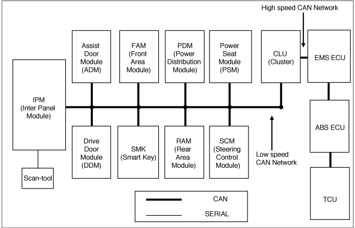
This code is outputted when IPM can't receive data from FAM by CAN Line for 10 sec.
Item | Detecting Condition | Possible Cause |
DTC Strategy | ● CAN Comm. Check (IPM ↔ FAM) | ● Check FAM connection ● Check fuse related FAM ● Check open in CAN high/low circuit of FAM ● Check open in CAN high/low circuit of FAM |
Enable Conditions | ● IPM power on | |
Threshold Value | ● No message from FAM to IPM for 10 sec. | |
Diagnostic Time | ● 10 sec | |
DTC Erasing Time | ● DTC is erased immediately after receiving data from FAM. |
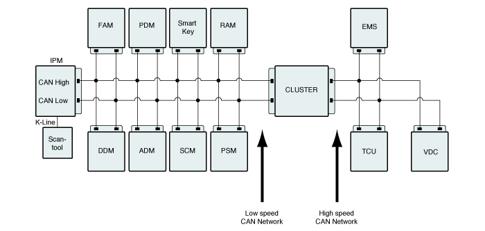
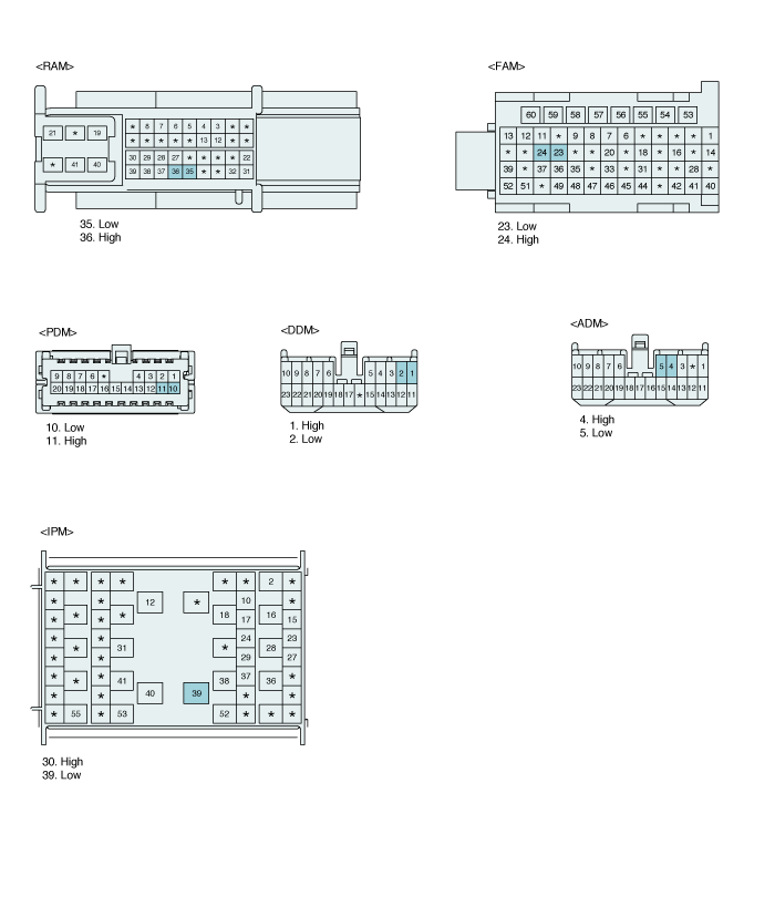
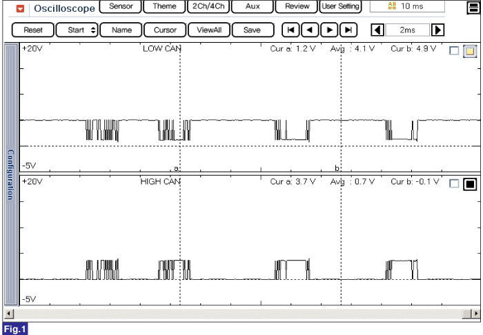
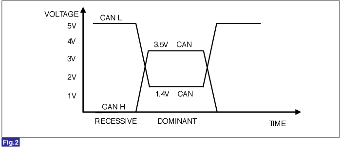
Fig 1) Signal waveform of CAN Low and HIGH
Fig 2) CAN BUS VOLTAGE LEVEL (LOW SPEED CAN)
Connect GDS.
IG "ON" and engine "OFF".
Select "DTC Analysis" mode.
After erase DTC, keep the vehicle condition within "the enable conditions" (Refer to "DTC Detecting Condition" table).

Is the same DTC occurred again?
 | ▶ Go to next procedure. |
 | ▶ Fault is intermittent caused by poor contact in IPM's and/or FAM's connector or was repaired and IPM memory was not cleared. Thoroughly check connectors for looseness, poor connection, bending, corrosion, contamination, deterioration, or damage. Repair or replace as necessary and then go to "Verification of Vehicle Repair" procedure. |
Many malfunctions in the electrical system are caused by poor harness(es) and terminals. Faults can also be caused by interference from other electrical systems, and mechanical or chemical damage.
Thoroughly check connectors for looseness, poor connection, bending, corrosion, contamination, deterioration, or damage.
Has a problem been found?
 | ▶ Repair as necessary and go to "Verification of Vehicle Repair" procedure. |
 | ▶ Go to " Signal Circuit Inpsection " procedure. |
Check CAN high circuit
IG "ON" & ENG "OFF"
Connect GDS and select Scope meter fucntion.
Measure signal waveform of FAM CAN High line.
Specification : Refer to signal waveform and data
Is the measured signal waveform of CAN high circuit normal ?
 | ▶ Go to next procedure. |
 | ▶ Check short to battery / ground in CAN high circuit, and repair or replace as necessary. Go to "Verification of Vehicle Repair" procedure. |
Check CAN Low circuit
IG "ON" & ENG "OFF"
Connect GDS and select Scope meter fucntion.
Measure signal waveform of FAM CAN Low line.
Specification : Refer to signal waveform and data
Is the measured signal waveform of CAN low circuit normal ?
 | ▶ Go to next procedure. |
 | ▶ Check short to battery / ground in CAN low circuit and, repair or replace as necessary. And then, go to 'Verification of Vehicle Repair" procedure. |
Check internal errors of CAN communication units.
Connect GDS.
IG "ON" and engine "OFF".
Select "DTC Analysis" mode.
Disconnect FAM and monitor DTC to find the cause.
Is the code erased?
 | ▶ Substitute with a known - good unit and check for proper operation. If the problem is corrected, replace the unit and go to "Verification of Vehicle Repair" procedure. |
 | ▶ Thoroughly check connectors for looseness, poor connection, bending, corrosion, contamination, deterioration, or damage. Repair or replace as necessary and go to "Verification of Vehicle Repair" procedure. |
After a repair, it is essential to verify that the fault has been corrected.
Connect scan tool and select "DTC Analysis" mode.
Clear the DTCs and Operate the vehicle within DTC Enable conditions in General information.
Is any DTC outputted again?
 | ▶ Go to the applicable troubleshooting procedure. |
 | ▶ System performing to specification at this time. |