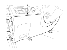
Remove the crash pad lower panel (A).
(Refer to the Body group - crash pad)

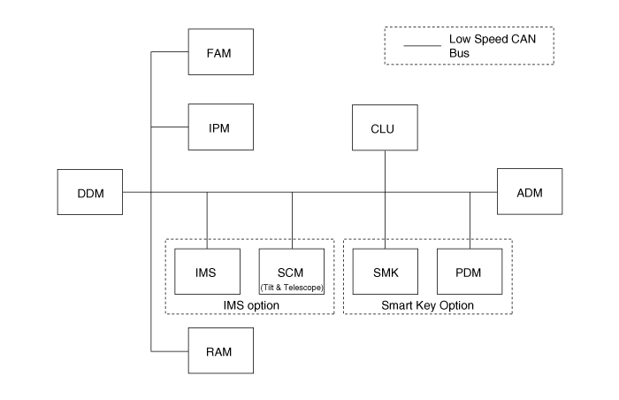
The body network system consists of several Modules that communicates via a CAN bus. The diagnostic tester is not directly connected to the CAN bus, but utilizes a one-wire communication line (K-line) that connects to a gateway in the IPM ECU.
The IPM communicates with the diagnostic tester directly. But other units operate self diagnostic, input/output monitoring and actuator operation via the IPM using the CAN communication.

No. | Input switch | Unit |
1 | IPM Node Availability | PRESENT/NOT PRESENT |
2 | FAM Node Availability | PRESENT/NOT PRESENT |
3 | RAM Node Availability | PRESENT/NOT PRESENT |
4 | DDM Node Availability | PRESENT/NOT PRESENT |
5 | ADM Node Availability | PRESENT/NOT PRESENT |
6 | IMS Node Availability | PRESENT/NOT PRESENT |
7 | CLU Node Availability | PRESENT/NOT PRESENT |
8 | SCM Node Availability | PRESENT/NOT PRESENT |
9 | SMK Node Availability | PRESENT/NOT PRESENT |
10 | PDM Node Availability | PRESENT/NOT PRESENT |
11 | IPM Node Failure | FAILURE/ O.K |
12 | FAM Node Failure | FAILURE/ O.K |
13 | RAM Node Failure | FAILURE/ O.K |
14 | DDM Node Failure | FAILURE/ O.K |
15 | ADM Node Failure | FAILURE/ O.K |
16 | IMS Node Failure | FAILURE/ O.K |
17 | CLU Node Failure | FAILURE/ O.K |
18 | SMK Node Failure | FAILURE/ O.K |
20 | PDM Node Failure | FAILURE/ O.K |
21 | Auto Head lamp | ON/OFF |
22 | Headlamp low beam | ON/OFF |
23 | Headlamp high beam | ON/OFF |
24 | Rear fog lamp | ON/OFF |
25 | Front fog lamp | ON/OFF |
26 | Park tail lamp | ON/OFF |
27 | Main room lamp | ON/OFF |
28 | Left turn signal | ON/OFF |
29 | Right turn signal | ON/OFF |
30 | Front wiper low speed switch(from multi function switch) | ON/OFF |
31 | Front wiper high speed switch(from multi function switch) | ON/OFF |
32 | Rear wiper low speed switch | ON/OFF |
33 | Rear wiper intermittent switch | ON/OFF |
34 | Front wiper intermittent switch | ON/OFF |
35 | Front washer | ON/OFF |
36 | Rear washer | ON/OFF |
37 | Windshield defogger | ON/OFF |
38 | Rear defogger | ON/OFF |
39 | Parking brake | ON/OFF |
40 | Hazard lamp switch | ON/OFF |
41 | Seat-belt | ON/OFF |
42 | Front headlamp washer switch | ON/OFF |
43 | Front wiper mist switch | ON/OFF |
44 | Headlamp high beam passing switch | ON/OFF |
45 | Ignition key reminder | INSERTED/NOT INSERTED |
46 | Crash sensor input from airbag unit | ON/OFF |
47 | IGN1 | ON/OFF |
48 | IGN2 | ON/OFF |
49 | ACC | ON/OFF |
50 | Hood Open switch | OPEN/CLOSED |
No. | Input switch | Unit |
1 | Inhibitor Switch Neutral | ON/OFF |
2 | Inhibitor Switch Park | ON/OFF |
3 | Inhibitor Switch Reverse | ON/OFF |
4 | Brake Fluid Sensor State | OK/LOW |
5 | Washer Fluid Sensor State | OK/LOW |
6 | Fuel Filter State | OK/NG |
7 | Oil Pressure Switch State | OK/LOW |
8 | IGN2 | ON/OFF |
9 | Front Wiper Park Switch State | Park/Out of park |
10 | Windshield defogger operation check | OK/NG |
No. | Input switch | Unit |
1 | Shift lever “P” position switch | ON/OFF |
2 | Passenger Door Open Switch | ON/OFF |
3 | Driver Door Open Switch | OPEN/CLOSE |
4 | Tailgate Door Open Switch | OPEN/CLOSE |
5 | RRD Open Switch | OPEN/CLOSE |
6 | RLD Open Switch | OPEN/CLOSE |
7 | RRD Power Window Up Switch | ON/OFF |
8 | RRD Power Window Down Switch | ON/OFF |
9 | RLD Power Window Up Switch | ON/OFF |
10 | RLD Power Window Down Switch | ON/OFF |
11 | RLD Lock Monitoring Switch | Lock/Unlock |
12 | RRD Lock Monitoring Switch | Lock/Unlock |
13 | IGN2 | ON/OFF |
14 | Rear Wiper Park Switch | Park/Out of park |
15 | Rear defogger operation check input | ON/NG |
No. | Input switch | Unit |
1 | Door Lock Monitoring Switch | LOCK/UNLOCK |
2 | Door Lock Switch | ON/OFF |
3 | Door Unlock Switch | ON/OFF |
4 | Key Cylinder Door Lock Switch | ON/OFF |
5 | Key Cylinder Door Unlock Switch | ON/OFF |
6 | Fuel Filler Door Open Switch | ON/OFF |
7 | OSRVM(Outside Rearview Mirror) Select Switch | RH/LH/OFF |
8 | OSRVM direction Select Switch | RIGHT/LEFT/DOWN/UP/OFF |
9 | OSRVM Folding/Unfolding Switch | Folding/Unfolding |
10 | IGN 2 Switch | ON/OFF |
11 | Window Lock Switch | ON/OFF |
12 | Front Left Window Up Switch | ON/OFF |
13 | Front Left Window Down Switch | ON/OFF |
14 | Front Left Window Auto Up Switch | ON/OFF |
15 | Front Left Window Auto Down Switch | ON/OFF |
16 | Front Right Window Up Switch | ON/OFF |
17 | Front Right Window Down Switch | ON/OFF |
18 | Front Right Window Auto Up Switch | ON/OFF |
19 | Front Right Window Auto Down Switch | ON/OFF |
20 | Rear Right Window Up Switch | ON/OFF |
21 | Rear Right Window Down Switch | ON/OFF |
22 | Rear Left Window Up Switch | ON/OFF |
23 | Rear Left Window Down Switch | ON/OFF |
No. | Input switch | Unit |
1 | Door Lock Monitoring Switch | ON/OFF |
2 | Door Lock Switch | ON/OFF |
3 | Door Unlock Switch | ON/OFF |
4 | Key Cylinder Door Lock Switch | ON/OFF |
5 | Key Cylinder Door Unlock Switch | ON/OFF |
6 | IGN2 Switch | ON/OFF |
7 | Front Right Window Up Switch | ON/OFF |
8 | Front Right Window Down Switch | ON/OFF |
9 | Front Right Window Auto Up Switch | ON/OFF |
10 | Front Right Window Auto Down Switch | ON/OFF |
No. | DTC Code | DTC | Possible cause |
1 | B1102 | Battery Voltage Low | Vbat<9V |
2 | B1581 | Ignition Switch Error | IG sw input is not coherent for more than 2s |
2 | B1588 | FR Wiper/washer MF SW | MF switch status is not coherent for more than 2s |
3 | B1589 | RR Wiper/washer MF SW | |
4 | B1590 | Light MF SW Error | MF switch status is not coherent for more than 2s |
5 | B1591 | Turn Signal MF SW Error | |
6 | B1602 | CAN Bus Physical Bus Failure | Physical error indicated by network management |
7 | B1605 | DDM COMM. Lost&bus Failure | DDM is missing in system configuration information reported from network management. |
8 | B1606 | ADM COMM. Lost&bus Failure | ADM is missing in system configuration information reported from network management. |
9 | B1607 | IMS COMM. Lost&bus Failure | IMS is missing in system configuration information reported from network management. |
10 | B1608 | Lost Communication With SCM, Bus Failure | SCM is missing in system configuration information reported form network management. |
11 | B1609 | Lost communication with SMK, bus failure | SMK is missing in system configuration information reported from network management |
12 | B1611 | FAM COMM. Lost&bus Failure | FAM is missing in system configuration information reported from network management. |
13 | B1612 | RAM COMM. Lost&bus Failure | RAM is missing in system configuration information reported from network management. |
14 | B1613 | CLU COMM. Lost&bus Failure | CLU is missing in system configuration information reported from network management. |
15 | B1624 | EEPROM Failure | Failed attempt to read or write EEPROM |
16 | B1627 | EEPROM Corruption | Data in EEPROM is not coherent |
17 | B1628 | Module CONF. Conflict | Hardware and software configuration are not coherent |
18 | B1646 | S/W Rescue Mode | Module enters rescue mode |
19 | B1681 | Lost communication with PDM, bus failure | PDM is missing in system configuration information reported from network management. |
No. | DTC Code | DTC | Possible cause |
1 | B1624 | EEPROM Failure | Failed attempt to read or write EEPROM |
2 | B1627 | EEPROM Corruption | Data in EEPROM is not coherent |
3 | B1646 | S/W Rescue Mode | As soon as the module enters rescue mode |
4 | B2119 | Windshield Defog Relay Fail | Windshield defog relay failure |
5 | B2535 | Right T/signal Lamp Short To Gnd | Right turn signal lamp circuit short to ground error |
6 | B2537 | Right T/signal Lamp Open | Right turn signal lamp circuit open error |
7 | B2539 | Left T/signal Lamp Short To Gnd | Left turn signal lamp circuit short to ground error |
8 | B2541 | Left T/signal Lamp Open | Left turn signal lamp circuit open error |
9 | B2543 | Right H/lamp High Short To Gnd | Right headlamp high circuit short to ground error |
10 | B2545 | Right H/lamp High Open | Right headlamp high circuit open error |
11 | B2547 | Left H/lamp High Short To Gnd | Left headlamp high circuit short to ground error |
12 | B2549 | Left H/lamp High Open | Left headlamp high circuit open error |
13 | B2551 | Right H/lamp Low Short To Gnd | Right headlamp low circuit short to ground error |
14 | B2553 | Right H/lamp Low Open | Right headlamp low circuit open error |
15 | B2555 | Left H/lamp Low Short To Gnd | Left headlamp low circuit short to ground error |
16 | B2557 | Left H/lamp Low Open | Left headlamp low circuit open error |
17 | B2559 | Fr Fog Lamp Short To Gnd | Right front fog lamp circuit short to ground error |
18 | B2561 | FR Fog Lamp Open | Right front fog lamp circuit open error |
19 | B2563 | FL Fog Lamp Short To Gnd | Left front fog lamp circuit short to ground error |
20 | B2565 | FL Fog Lamp Open | Left front fog lamp circuit open error |
21 | B2571 | Right P/lamp Short To Gnd | Right parking lamp circuit short to ground error |
22 | B2573 | Right P/lamp Open | Right parking lamp circuit open error |
23 | B2575 | Left P/lamp Short To Gnd | Left parking lamp circuit short to ground error |
24 | B2577 | Left P/lamp Open | Left parking lamp circuit open error |
No. | DTC Code | DTC | Possible cause |
1 | B1624 | EEPROM Failure | Failed attempt to read or write EEPROM |
2 | B1627 | EEPROM Corruption | Data in EEPROM is not coherent |
3 | B1646 | S/W Rescue Mode | As soon as the module enters rescue mode |
4 | B2115 | Rear Defog Relay Fail | Command active and check entry not active |
5 | B2441 | RR Wiper P. POS. Detect Fail | Command active and park position does not change during 5s |
6 | B2535 | Right T/signal Lamp Short To Gnd | Right turn signal lamp circuit short to ground error |
7 | B2537 | Right T/signal Lamp Open | Right turn signal lamp circuit open error |
8 | B2539 | Left T/signal Lamp Short To Gnd | Left turn signal lamp circuit short to ground error |
9 | B2541 | Left T/signal Lamp Open | Left turn signal lamp circuit open error |
10 | B2579 | RR Tail Marker Lamp Short To Gnd | Right tail license side marker lamp circuit short to ground error |
11 | B2581 | RR Tail Marker Lamp Open | Right tail license side marker lamp circuit open error |
12 | B2583 | RL Tail Marker Lamp Short To Gnd | Left tail license side marker lamp circuit short to ground error |
13 | B2585 | RL Tail Marker Lamp Open | Left tail license side marker lamp circuit open error |
14 | B2587 | Back Up Lamp Short To Gnd | Back up lamps for Back Up Warning System unit circuit short to ground error |
15 | B2589 | Back Up Lamp Open | Back up lamps for Back Up Warning System unit circuit open error |
16 | B2599 | RR Blower SW ILLU. Short To Gnd | Rear blower switch illumination short to ground |
No. | DTC Code | DTC | Possible cause |
1 | B1603 | CAN Bus error | CAN communication error |
2 | B1910 | Left OSM horizontal motor or sensor error | Right OSM horizontal motor circuit open error |
3 | B1911 | Left OSM vertical motor or sensor error | Right OSM horizontal motor circuit open error |
4 | B1952 | OSRVM defogger error | Left OSM deicer circuit open error |
5 | B2330 | Driver door lock actuator error | Assist door lock actuator circuit open error |
6 | B2331 | Driver door unlock actuator error | Assist door unlock actuator circuit open error |
7 | B2529 | Drive door courtesy lamp error | Driver door courtesy lamp circuit open error |
No. | DTC Code | DTC | Possible cause |
1 | B1603 | CAN Bus error | CAN communication error |
2 | B1912 | Right OSM horizontal motor or sensor error | Right OSM horizontal motor circuit open error |
3 | B1913 | Right OSM vertical motor or sensor error | Right OSM horizontal motor circuit open error |
4 | B1952 | OSRVM defogger error | Right OSM deicer circuit open error |
5 | B2332 | Assist door unlock actuator error | Assist door lock actuator circuit open error |
6 | B2333 | Assist door unlock actuator error | Assist door unlock actuator circuit open error |
7 | B2533 | Assist door courtesy lamp error | Assist door courtesy lamp circuit open error |
No. | DTC Code | DTC | Possible cause |
1 | B1954 | Slide motor or sensor error | Lost Communication With Slide motor sensor output for more than 2 s |
2 | B1955 | Recline motor or sensor error | Lost Communication With Recline motor sensor output for more than 2 s |
3 | B1956 | Front height motor or sensor error | Lost Communication With Front right motor sensor output for more than 1 s |
4 | B1957 | Rear height motor or sensor error | Lost Communication With Rear right motor sensor output for more than 1 s |
No. | DTC Code | DTC | Possible cause |
1 | B1959 | Tilt motor or sensor errer | - |
2 | B1960 | Tele motor or sensor error | - |
No. | Description | Value | Control |
1 | Windshield Defog Switch Indicator Output | ON/OFF | Continuously ON |
2 | Rear Defog Switch Indicator Output | ON/OFF | Continuously ON |
3 | Rear Fog Lamp Switch Indicator Output | ON/OFF | Continuously ON |
4 | Back Up Signal Output | ON/OFF | Continuously ON |
5 | Micro Burglar Relay Drive Output | ON/OFF | Continuously ON |
6 | Ignition Key Hole Illumination | ON/OFF | Continuously ON |
7 | Adjustable Pedal On Off Signal Output | ON/OFF | Continuously ON |
8 | Power Feed To Sunroof Relay Coil | ON/OFF | Continuously ON |
9 | Horn Relay Drive | ON/OFF | 0.5 sec ON then OFF |
10 | Sound Mute Signal Output | ON/OFF | Continuously ON |
11 | Panel Lights Trip Computer Output | ON/OFF | Continuously ON |
12 | Burglar Alarm Indicator | ON/OFF | Continuously ON |
13 | AV Tail Output | ON/OFF | Continuously ON |
14 | Chime | ON/OFF | Continuously ON with 0.6 sec period |
No. | Description | Value | Control |
1 | Front Washer | ON/OFF | 1 sec ON then OFF (once) |
2 | Rear Washer | ON/OFF | 2 sec ON then OFF (once) |
3 | Right Headlamp High | ON/OFF | Continuously ON |
4 | Right Headlamp Low | ON/OFF | Continuously ON |
5 | Right Lamp Park | ON/OFF | Continuously ON |
6 | Right Fog Lamp | ON/OFF | Continuously ON |
7 | Right Turn Signal | ON/OFF | Continuously ON with (80 +/- 5) cycles per minute, Duty: 50% |
8 | Left Headlamp High | ON/OFF | Continuously ON |
9 | Left Headlamp Low | ON/OFF | Continuously ON |
10 | Left Lamp Park | ON/OFF | Continuously ON |
11 | Left Fog Lamp | ON/OFF | Continuously ON |
12 | Left Turn Signal | ON/OFF | Continuously ON with (80 +/- 5) cycles per minute, Duty: 50% |
13 | IGN2 Control | ON/OFF | Continuously ON |
14 | Headlamp washer | ON/OFF | Continuously ON |
15 | Windshield Defog Timer | ON/OFF | Continuously ON |
16 | Wiper On Off | ON/OFF | Continuously ON |
17 | Wiper Low speed | ON/OFF | 3 wiping with LOW speed |
18 | Wiper High speed | ON/OFF | 3 wiping with HIGH speed |
19 | Burglar Alarm horn | ON/OFF | Continuously ON with 60 cycles per minute, Duty:50% |
No. | Description | Value | Control |
1 | Room Lamp LS | ON/OFF | Continuously ON |
2 | Room Lamp LS Door | ON/OFF | Continuously ON |
3 | Luggage Lamp LS | ON/OFF | Continuously ON |
8 | RRD Power Window Up | ON/OFF | 3 sec ON then OFF (once) |
9 | RRD Power Window Down | ON/OFF | 3 sec ON then OFF (once) |
10 | RLD Power Window Up | ON/OFF | 3 sec ON then OFF (once) |
11 | RLD Power Window Down | ON/OFF | 3 sec ON then OFF (once) |
12 | RR Seat Warmer switch | ON/OFF | Continuously ON |
13 | RL Seat Warmer switch | ON/OFF | Continuously ON |
14 | ATM shift lock solenoid | ON/OFF | Continuously ON |
15 | Key interlock solenoid | ON/OFF | Continuously ON |
16 | Tailgate unlock signal | ON/OFF | Continuously ON |
17 | Rear Defogger | ON/OFF | Continuously ON |
18 | Rear Fog Lamps | ON/OFF | Continuously ON |
19 | Right Turn Signal Lamp | ON/OFF | Continuously ON with (80 +/- 5) cycles per minute, Duty: 50% |
20 | Left Turn Signal Lamp | ON/OFF | Continuously ON with (80 +/- 5) cycles per minute, Duty: 50% |
21 | Back Up Lamp Back Up Warning System Unit | ON/OFF | Continuously ON |
22 | Left/Right Tail License Side Marker | ON/OFF | Continuously ON |
23 | Door Lock | ON/OFF | 0.5 sec ON then OFF (once) |
24 | Door Unlock | ON/OFF | 0.5 sec ON then OFF (once) |
25 | Rear Wiper Motor | ON/OFF | 5 sec ON then OFF (once) |
26 | Rear Monitor illumination | ON/OFF | Continuously ON |
27 | Fuel Filler Door Solenoid | ON/OFF | 0.5 sec ON then OFF (once) |
28 | Map Lamp LS | ON/OFF | Continuously ON |
No. | Description | Value | Control |
1 | Door Courtesy Lamp | ON/OFF | Continuously ON |
2 | Door Lock Out | ON/OFF | 0.5 sec ON then OFF (once) |
3 | Door Unlock Out | ON/OFF | 0.5 sec ON then OFF (once) |
4 | OSRVM Up | ON/OFF | 3 sec ON then OFF (once) |
5 | OSRVM Down | ON/OFF | 3 sec ON then OFF (once) |
6 | OSRVM Left | ON/OFF | 3 sec ON then OFF (once) |
7 | OSRVM Right | ON/OFF | 3 sec ON then OFF (once) |
8 | OSRVM Defogger | ON/OFF | Continuously ON |
9 | Power Window up Out | ON/OFF | 3 sec ON then OFF (once) |
10 | Power Window Down Out | ON/OFF | 3 sec ON then OFF (once) |
11 | Illumination Out | ON/OFF | Continuously ON |
12 | OSRVM Folding | ON/OFF | Continuously ON |
13 | OSRVM Unfolding | ON/OFF | Continuously ON |
14 | OSRVM Turn signal lamp | ON/OFF | Continuously ON |
No. | Description | Value | Control |
1 | Power Seat Slide Forward Motor | ON/OFF | Continuously ON |
2 | Power Seat Slide Backward Motor | ON/OFF | Continuously ON |
3 | Power Seat FR Height Up Motor | ON/OFF | Continuously ON |
4 | Power Seat FR Height Down Motor | ON/OFF | Continuously ON |
5 | Power Seat RR Height Up Motor | ON/OFF | Continuously ON |
6 | Power Seat RR Height Down Motor | ON/OFF | Continuously ON |
7 | Power Seat Recline Forward Motor | ON/OFF | Continuously ON |
8 | Power Seat Recline Backward Motor | ON/OFF | Continuously ON |
No. | Description | Value | Control |
1 | Steering Column Tilt Up Motor | ON/OFF | Continuously ON |
2 | Steering Column Tilt Down Motor | ON/OFF | Continuously ON |
3 | Steering Column Telescopic Forward Motor | ON/OFF | Continuously ON |
4 | Steering Column Telescopic Backward Motor | ON/OFF | Continuously ON |
Disconnect the negative (-) battery terminal.
Remove the crash pad lower panel (A).
(Refer to the Body group - crash pad)

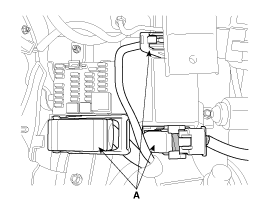
Remove IPM(Instrument Panel Module) connector(A)

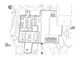
Remove IPM(Instrument Panel Module) after loosening mounting bolts(3EA).

Install IPM(instrument Panel Module)
Connect the IPM connector
Install the crash pad lower panel