3.
Monitor the "Engine Speed" parameter on the scan tool.
Specification : 600±100rpm RPM
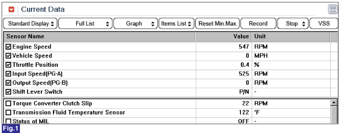
Fig 1) Engine RPM at Idle

Several control units are applied to electronically controlled vehicles. These units perform each control with informations from various sensors. Thus, sharing signal information from sensors is needed, so CAN communication type whose communication speed is high and insensitive to electrical noise by spark generation is adopted to controlling power-train(engine, atutomatic transaxle, ABS, TCS, ECS)
A/T, ESP, ABS control units share the informations that Engine rpm, APS signal, gear position, Torque reduction signal, using CAN communication to confirm active controlling.
TCM set this code If detected error in Engine rpm signal.(MIL ON : 2 driving Cycle)
Item | Detecting Condition | Possible Cause |
DTC Strategy | ● Check signal range | ● Check the Engine |
Enable Conditions | ● IG KEY "ON" ● CAN BUS : normal ● ECU CAN connect status : normal ● Battery voltage > 9V | |
Threshold Value | ● Circuit malfunction | |
Diagnostic Time | ● 1 second | |
Fail Safe | ● Maximum line pressure control(D : 14kg/㎠, R : 20kg/㎠) ● Inhibite Torque convertor clutch control ● Shift lock release ● No learning control ● Keep the present gear ● Fixed at 3rd gear (In case of CASE2 : possible to normal shifting) (priority : 3) |
The function with the higher priority will aiways take precedence. However, a low-priority is not overruled by a higher priority function.
Functions from different priority categories can also run in parallel. It is important to note which function will take precedence in this case.
In such an event it is possible for a substitute function with low priority not be carried out if a second, higher-priority function is present. This has been taken into account when compiling the priority list and is international.
The mechanical emergency run function must always have the highest priority, since from the electrical standpoint it is the only safe condition.
Fig 1) Engine rpm When Idle
Connect scantool to Diagnostic Connector.
Ignition "ON" & Engine "OFF".
Monitor the "Engine Speed" parameter on the scan tool.
Specification : 600±100rpm RPM
Fig 1) Engine RPM at Idle
Is "Engine Speed" output value within specification ?
 | ▶ Fault is intermittent caused by poor contact in the sensor's and/or TCM(PCM)'s connector or was repaired and TCM(PCM) memory was not cleared. Throughly check connectors for looseness, poor connection, bending, corrosion, contamination, deterioration or damage.Repair or replace as necessary and go to "Verification Vehicle Repair" procedure. |
 | ▶ Go to "Component Inspection" procedure. |
Ignition "ON" & Engine "OFF".
Connect scantool and check DTC.
Erase the DTC with scantool.
After turning IG OFF to IG ON twice or three times, check DTC again.
Does the scantool show same DTC again ?
| ▶ Substitute with a known-good Mechatronics (Valve-body + TCM) and check for proper operation. If the problem is corrected,replace Mechatronics (Valve-body + TCM) and then go to "Verification of Vehicle Repair" procedure. |
| ▶ Fault is intermittent caused by poor contact in the sensor’s and/or PCM’s connector or was repaired and PCM memory was not cleared. Thoroughly check connectors for looseness, poor connection, ending, corrosion, contamination, deterioration, or damage. Repair or replace as necessary and go to "Verification of Vehicle Repair" procedure. |
How to perform Initial Learning
If you replace the automatic transmission or Mechatronics (Valve-body + TCM), or if you overwrite the TCU software, be sure to initialize the learned values and perform initial learning.
Step 1) Warm-up
Raise the ATF temperature by leaving the vehicle idling or performing city drive. Check the ATF temperature using the Scan-tool and make sure it is between 50°C( 122 °F) and 120°C( 248 °F). If the ATF temperature is outside this range, work to bring the range.
Don't raise the oil temperature by stalling the engine.
(Reference)
If the oil temperature is not between 50°C( 122 °F) and 120°C ( 248 °F), initial learning can not be performed. Before learning, check for variable speed shock or shift shock.
STEP 2) Driving learning
Select "D" range then depress accelerator pedal smoothly, and keep the APS value 17%, shift gear to 5th gear.
RKeep the vehicle speed over 60kM/h.
In condition that release the accelerator pedal and then depress the brake pedal narmally.Stop the vehicle then keep 5seconds.
STEP 3) Repeat this procedure 10 times.(Not necessary N-D,N-R Learning)
After a repair, it is essential to verify that the fault has been corrected.
Connect scantool and select "Diagnostic Trouble Codes(DTCs)" mode.
Using a scan tool, Clear DTC.
Operate the vehicle within DTC Enable conditions in General information.
Are any DTCs present ?
| ▶ Go to the applicable troubleshooting procedure. |
| ▶ System performing to specification at this time. |
