1.
Measure the voltage between "Power" terminal of "IGNITION COIL" harness connector and chassis ground with IG key "ON" after disconnecting "IGNITION COIL" connector.
■ Specification : B+
Measure the voltage between "Power" terminal of "IGNITION COIL" harness connector and chassis ground with IG key "ON" after disconnecting "IGNITION COIL" connector.
■ Specification : B+
Is the voltage within the specification?
 | ▶ Go to "Ignition coil control circuit inspection" procedure as below. |
 | ▶ Check for open/poor connection/short to ground between "IGN COIL FUSE 20A" and "Power" terminal of the "IGNITION COIL" harness connector. |
Connect the red tongs of the LED circuit tester to battery (+) and probe of LED circuit tester to "Control" terminal of "IGNITION COIL" harness connector after disconnecting "IGNITION COIL" connector.
Perform actuation test "Ignition coil #1~#8"
Is the LED circuit tester lit (When ignition coil is operated by actuation test)?
| ▶ Go to "Ignition coil signal waveform inspection" procedure as below. |
| ▶ Check for open/poor connection/short to ground between "Ignition Coil Control" terminal of the "ECM" harness connector and "Control" terminal of the "IGNITION COIL" harness connector. |
Select oscilloscope function on the GDS and Connect channel "A" of the VMI to "Control" terminal of the "ECM" harness connector.
Measure the 1st ignition coil signal waveform with IG key "START".
■ Reference signal waveform
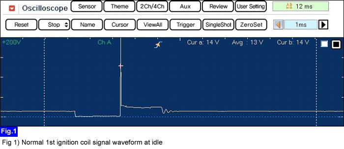
Is the 1st ignition coil signal waveform normal?
| ▶ There are possible causes as below. Click on each item for more details. "Spark plug", "MAFS", "TPS" |
| ▶ Check for open/poor connection/short to ground between "Ignition Coil Control" terminal of the "ECM" harness connector and "Control" terminal of the "IGNITION COIL" harness connector. |
