
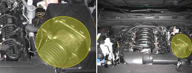
The Mass Air Flow Sensor (MAFS) is located between the air cleaner assembly and the throttle body. The MAFS uses a hot film type sensing element to measure the mass of intake air entering the engine. This hot film type air flow sensor consists of a hot film sensor, housing and metering ducts. Mass air flow rate is measured by detection of heat transfer from a hot film probe. The change in air flow rate causes change in the amount of heat being transferred from the hot film probe surface to the air. A large amount of intake air represents acceleration or high load conditions while a small amount of intake air represents deceleration or idle. The mass of intake air should increase at acceleration and be stable during constant engine speed. The ECM uses this information to determine the injection duration and ignition timing for the desired air/fuel ratio.
If the deviation between the inlet air mass by MAF signal and the ECM model value is out of the threshold value, ECM sets P0101.
Item | Detecting Condition | ||
Case1 | DTC Strategy |
•
Range Check |
•
Clogged air cleaner
•
MAFS |
Enable Conditions |
•
Crank rev. 150rev | ||
Threshold Value |
•
Mass flow >1200kg/h or < -200kg/h | ||
Diagnostic Time |
•
2 sec | ||
Case2 | DTC Strategy |
•
Rationality Check | |
Enable Conditions |
•
TPS >15% , Engine speed >1500rpm or TPS <4% , Engine speed < 800rpm | ||
Threshold Value |
•
Mass Flow /Max Model Mass Flow > 5.26% or Min Model Mass Flow/Mass Flow >4% | ||
Diagnostic Time |
•
2 sec | ||
Case3 | DTC Strategy |
•
Stuck Check | |
Enable Conditions |
•
Crank rev. 150rev
•
ETC NO Error | ||
Threshold Value |
•
Delta Mass Flow < 2kg/h | ||
MIL ON Condition |
•
2 driving cycle | ||
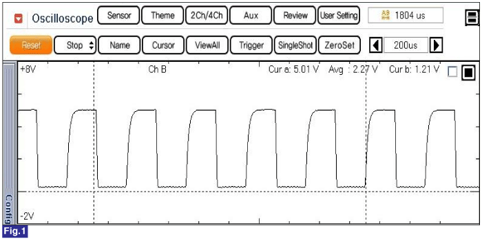
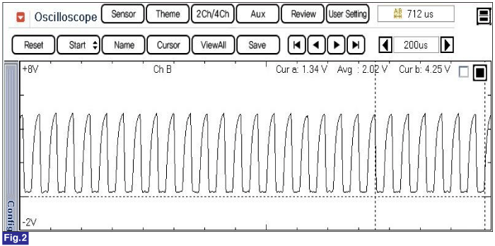
Fig.1) Normal waveform of MAFS at idle.
Fig.2) Normal waveform of MAFS at acceleration.
