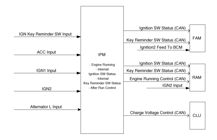
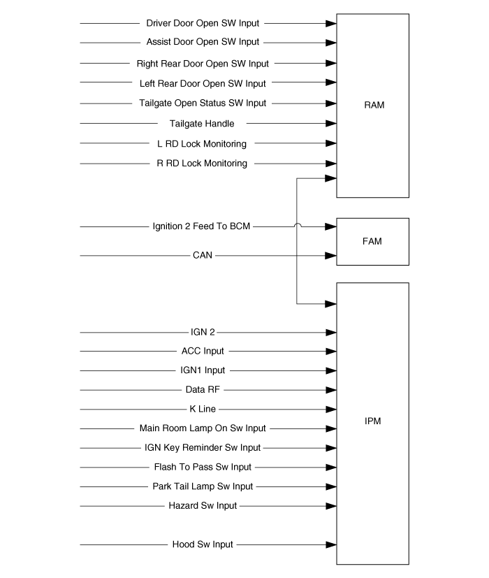
This function managed by the IPM, controls :
Ignition key position in the key cylinder (off, acc, run , start)
Ignition key reminder status (inserted or not)
Engine running status
Charging voltage
The data are transmitted on the CAN.
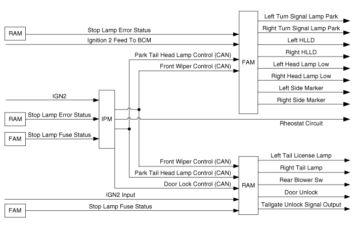
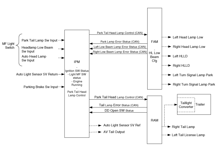
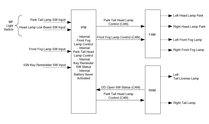
The MF Light switch is used to manage the park lamps, the tail lamps and the headlamps low beam.
The park lamps, the tail lamps and the headlamps low beam status are determined by:
The light MF switch:
1) The MF light switch has 4 positions: OFF, Park and Tail, Headlamps Low Beam, Auto light
2) It is connected to the IPM with 3 wires: Park and Tail lamp Sw, Headlamp Sw, Auto light Sw
The Auto light function
The Battery Saver function
The Auto light function is active when the MF Light sw is in Auto light position and depends on the ignition key position.
Based on the Auto light sensor values corresponding to the exterior brightness level, it automatically manages the lighting of the park lamps, the tail lamps and the headlamps low beam. Depending on the country, these lamps are controlled either separately or together.
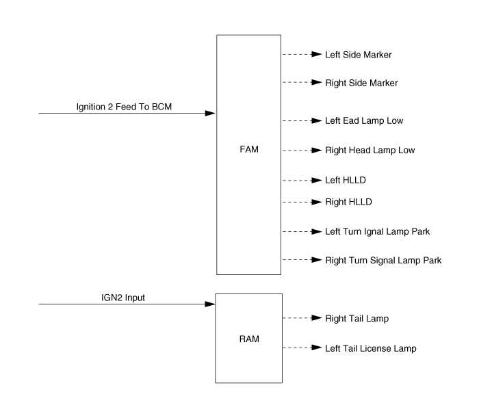
The IPM manages the control logic of the functions, and sends the command to the RAM and the FAM that drive the lamps.
The FAM drives the turn signal park lamps and the side marker lamps. All these lamps are controlled simultaneously. The FAM also drives the headlamps low beam and the HLLD, both in same time.
The RAM drives the tail lamps. Moreover, when the tail lamps are switched on, the license plate lamps are also lighted on.
For each of the park lamps, the tail lamps and the headlamps low beam, a status message is sent by FAM or RAM to the IPM and to CLU to indicate if one lamp is in error.
The light MF switch is connected to the IPM and is used to command the park lamps, tail lamps and the headlamps low beam.
MF Light sw status definition:
Park Tail Lamp SW Input | Headlamp Low Beam SW Input | Auto Headlamp SW Input | MF Light sw status |
Off | Off | Off | Off |
On | Off | Off | Park Tail |
On | On | Off | Low Beam |
On | On | On | Low Beam |
Off | Off | On | Auto |
The Auto light Sensor signal status value is defined thanks to the Auto light sensor value (input “Auto light sensor 5V return”).
Auto light Sensor signal Sts definition:
N° | Autolight Sensor 5V Return | Previous Value Of Auto Light Sensor 5V Return | Auto Light Sensor Signal Sts |
1 | > 3.47V | < 3.47V | Off |
2 | < 1.77V | > 1.77V | HL On |
These values can be calibrated on the real vehicle depending on the customer’s request. Thes calibrated values are prior to the specification.
The RAM drives the tail lamps.
Tail lamps truth table:
The tail lamps are controlled depending on the Park Tail Head Lamp control value.
Park Tail Head Lamp | Right Tail Lamp Left Tail License Lamp |
Off | Off |
Park Tail On | On |
Park Low Tail On | On |
The FAM drives either the side marker lamps or the turn signal park lamps.
The lamps are controlled simultaneously.
Park lamps truth table:
The park lamps are controlled depending on the Park Tail Head Lamp control value.
Park Tail Head Lamp | Left Turn Signal Lamp Park Right Turn Signal Lamp Park |
Off | Off |
Park Tail On | On |
Park Low Tail On | On |
The FAM also drives the Headlamps low beam and the HLLD, both simultaneously.
Headlamps low beam truth table:
The Headlamps low beams are controlled depending on the Park Tail Head Lamp Control value.
Park Tail Head Lamp | Left Head Lamp Low Right Head Lamp Low |
Off | Off |
Park Tail On | Off |
Park Low Tail On | On |
HLLD control:
The left and right HLLD are following the same control logic and the same requirements as the headlamps low beam.
The module drives left HLLD and right HLLD.
The following functions activate the Headlamps High Beam:
The High Beam switch,
The Flash To Pass switch,
The IPM manages the control logic of the functions, and sends the command to the FAM that drives the headlamps high beam lamps. CLU has a backlight indicator for the Headlamps High Beam.
A status message coming from the Left and Right Head lamps High Beam is sent by FAM to the IPM and to CLU to indicate if one lamp is in error.

The high beam lever (High Beam sw and Flash To Pass sw) is connected to the IPM and is used to command the headlamps high beam.
The IPM manages the control logic of all the functions concerned with the headlamps high beam. The command of those lamps is sent to the FAM thanks to the CAN signal High Beam control.
High beam lever in High Beam position:
In this lever position, the headlamps high beam is lighted ON when the ignition key position is RUN and if the headlamps low beam is also activated.
N° | High Beam | Flash To Pass | Ignition SW Status | Engine Running | Park Brake | MF Light SW Status | High Beam Control |
1 | On | Off | Run | Running | Off | Off | DRL On (*) |
2 | Park Tail | DRL On (*) | |||||
3 | Other Cases | Off | |||||
4 | Run | x | x | Low Beam | High On | ||
5 | Run | x | x | Auto | High On | ||
6 | Other Cases | Off | |||||
x : Not applicable
High beam lever in Flash To Pass position:
In this lever position, the headlamps high beam control logic only depends on the ignition key position.
N° | High Beam | Flash To Pass | Ignition SW Status | Engine Running | Park Brake SW | MF Light SW Status | High Beam Control |
1 | On | On | Off | x | x | x | High On |
2 | ACC | x | x | x | High On | ||
3 | Run | x | x | x | High On | ||
4 | Start | x | x | x | Off |
x : Not applicable
The FAM drives the headlamps high beam depending on the High Beam Ctrl:
Truth table for the Headlamps high beam:
High Beam Control | Left Head Lamp Highright Head Lamp High |
Off | Off |
High On | On |
DRL On | On DRL |
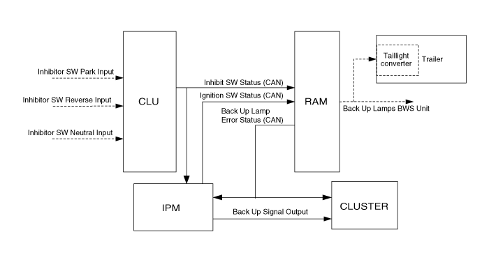
The backup lamps function switches on the backup lamps to indicate that the vehicle is in the reverse gear, it also switches on the backup signal output for cluster.
The CLU module sends the reverse gear status to the IPM and the RAM. The IPM drives the backup signal output for cluster and the RAM drives the backup lamps.
A status message is sent by RAM to the IPM and to CLU to indicate if one lamp is in error.
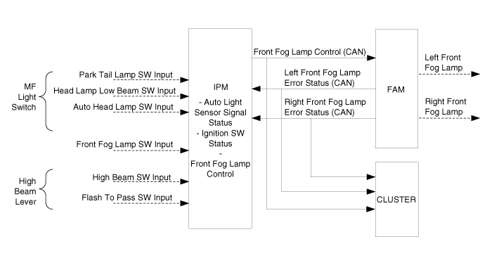
The front fog lamps are activated thanks to a switch connected to the IPM.
The IPM manages the control logic of the front fog function, and sends the command to the FAM that drives the front fog lamps.
A status message coming from the left and right front fog lamps is sent by FAM to the IPM to indicate if one lamp is in error or not.
The Battery Saver function provides an automatic shut off to the Park and Tail lamps (with the license plate lamps and the Side marker lamps) and to the Front fog lamps to save the power of the Battery.
The IPM manages the control logic of the function, and sends the command to the FAM and the RAM that drives the lamps.
The following requirements describe the conditions to activate and to deactivate the battery save function.
Working conditions for the battery Saver function for RKE equipped vehicle only:
The Battery Saver function is activated when Key Reminder Sw Sts is not inserted and the driver door is open (1). In this case, Battery Saver Activated is ON.
(1) Driver door open switch status is OPEN
Working conditions for the battery Saver function for SMK equipped vehicle:
The Battery Saver function is activated when Ignition Sw status is at OFF state and the driver door is open (1). In this case, Battery Saver Activated is ON.
(1) Driver door open switch status is OPEN
Battery Saver deactivation: key inserted for RKE equipped vehicle only
The battery saver function is deactivated when Key Reminder Sw Sts is inserted (Battery Saver Activated is OFF).
Battery Saver deactivation: for SMK equipped vehicle
The battery saver function is deactivated when a transition from OFF to ACC or IGN1 or ING2 for Ignition Sw Sts is detected (Battery Saver Activated is OFF).
Battery Saver activated: action of Driver door open switch status is OPEN
The battery saver is not deactivated when Driver door open switch status value changes.
Battery Saver deactivation: intentional “park and tail ON”
When the light MF is switched OFF and then set to 'Park and Tail lamps' or 'Headlamps low beam' positions (intentional “park and tail ON”), the Battery Saver function is deactivated.
In this case, Battery Saver Activated is OFF.
Battery Saver deactivation: reset of the intentional “park and tail ON” for SMK equipped vehicle only
When the light MF is switched OFF then set to 'Park and Tail lamps' or 'Headlamps low beam' positions (intentional “park and tail ON”), the Battery Saver function is deactivated (Battery Saver Activated is OFF) while the Ignition Sw Sts is at OFF position.
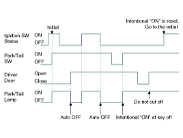
This time sequence diagram is true with an intentional “park and tail ON” due to ‘Head Lamp low beam’ switching sequence ON-> OFF-> ON : Park/Tail lamps are switched to ON.
Time sequence diagram for battery saver function
Battery Saver deactivation: reset of the intentional “park and tail ON” for RKE equipped vehicle
When the light MF is switched OFF then set to 'Park and Tail lamps' or 'Headlamps low beam' positions (intentional “park and tail ON”), the Battery Saver function is deactivated (Battery Saver Activated is OFF) while the Key Reminder Sw Sts is not inserted.
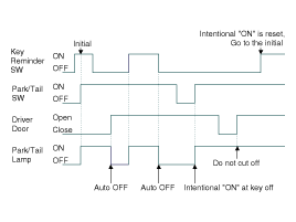
This time sequence diagram is true with an intentional “park and tail ON” due to ‘Head Lamp low beam’ switching sequence ON-> OFF-> ON : Park/Tail lamps are switched to ON.
Time sequence diagram for battery saver function
The turn signal lamps status is determined by:
The left and right turn signal switches
The hazard switch
The crash unlock activation
The RKE lock, unlock, tailgate unlock and panic signals
The alarm activation
A sound relay connected to the Cluster manages the “tick” sound during the turn signal lamps activation.
The cluster has two backlight indicators: one for the left Turn Signal lamps and one for the right Turn Signal lamps.
The IPM manages the control logic of the function, and sends the command to the FAM and the RAM that drives the turn signal lamps. The same CAN signal is used for the front and the rear turn signal activation.
The IPM manages the control logic of the turn signal function. The command of the turn signal lamps is sent to the FAM and the RAM thanks to the CAN signal Turn Indicator Ctrl.
Crash unlock mode:
When a crash unlock occurs, the CAN message Turn Indicator Ctrl is sent with the sequence values all on / all off at the frequency 80 (+/-5) cycles per minute (duty 50% +/-5%).
Crash unlock sequence stop:
The crash unlock flashing sequence stops when the ignition key is OFF.
Hazard mode: working conditions
The Hazard lamps sequence is activated when the hazard SW input is ON in any position of Ignition Sw.
Hazard mode: definition
When the Hazard lamps are activated by the Hazard button, Turn Indicator Ctrl is sent with the sequence values ALL ON / ALL OFF at the frequency (80 +/- 5) cycles per minute (duty 50% +/-5%).
Stop of the hazard mode:
The Hazard lamps sequence is stopped when the hazard SW input is off or when a higher priority sequence occurs.
The priorities between the different modes are:
Priorities between the turn signal commands:
The priorities between the different commands of the turn signal lamps from the upper to the lower priority are as following:
1st: Hazard lamps ordered by the Hazard switch
2nd: Hazard lamps ordered by the Crash Unlock activation
3rd: Alarm flashing sequence
4th: RKE panic signal flashing sequence
5th: RKE lock / unlock signal flashing sequence
6th: Left or Right Turn signal lamps ordered by the turn lever switch
The vehicle is equipped with Room Lamps located on the front and rear interior roof.
The lamps low sides are driven by the RAM, and the control logic depends on:
Front and rear doors status (RAM input)
Tailgate status
Lock/unlock interior lamp control information depending on RKE/SMK for vehicles not equipped with
Burglar Alarm (signal sent from IPM to RAM)
Lock/unlock interior lamp control information depending on Burglar Alarm state for vehicles equipped with Burglar Alarm (signals sent from IPM to RAM)
The ignition key position (managed by the IPM and signal transmitted to the RAM).
The Main Room Lamp switch (variation dependent equipment), which is a common control for the interior light.
Local 3-state switches (ON, OFF and DOOR positions) directly wired to the lamps can also be used to manually force the Room Lamp behavior. The RAM has no feedback of the local switches positions. No diagnostic (problem detection) is done on the Room Lamps.
The vehicle is equipped with a Luggage Lamp of which the low side is driven by the RAM, and the control logic depends on:
Tailgate status (RAM input)
The ignition key position (managed by the IPM and signal transmitted to the RAM).
The Main Room Lamp switch (variation dependent equipment), which is a common control for the interior light.
No diagnostic (problem detection) is done on the Luggage Lamps.
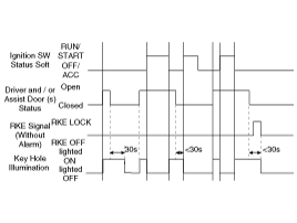
This function provides an illumination of the ignition key cylinder to help the driver inserting the key.
The key cylinder illumination depends on:
The driver and assist door status (open or close) provided by the RAM,
The ignition key position (off, acc, run, start) managed by the IPM,
Ignition key reminder (inserted or not) managed by the IPM,
The Burglar Alarm state managed by the IPM (depending on vehicle variation),
The keyhole illumination is switched on when receiving Driver door open switch status or Assist door open switch status CAN signals with open value.
The keyhole illumination is switched off 30s after Driver door open switch status or Assist door open switch status CAN signals were received with value close.
When the ignition key switch status is RUN or start, the keyhole illumination is off.
When the ignition key is in off or ACC position, and if any transition from closed to open is detected on the Driver or Assist door, then the key hole illumination is switched ON for 20minute and then off.
When the Driver or Assist door is open, and the ignition key position changes from run/start to off/ACC, then the keyhole illumination is switched ON for 20minute and then off.
When the system enters arm wait mode by Remote Key or Mechanical cylinder lock switches, the key hole illumination is switched off immediately.
If the keyhole is illuminated, and both the Driver and the Assist doors status changed to closed, then a 30-second timer is started.
The keyhole illumination is maintained on while this 30-second timer is running.
While running, this 30-second timer is restarted on reception of a Driver or the Assist doors status transition.
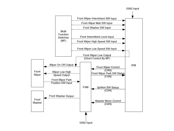
The vehicle is equipped with a Front Wiper and Washer, locally controlled (manual operation) by a MF switch.
This functionality is directly accessible to the driver. It consists in the possibility to activate or deactivate the wiper of the front windshield. When the driver decides to activate the front wiper, he has to choose between several modes of operation using the MF switch:
Continuous low speed;
Continuous high speed;
Auto (intermittent) mode (5 levels)
Another switch is used for the front washer. It consists in activating the front washer pump, which is located under hood. The washer activation has a consequence on the activation of the front wiper in order to clean the windshield.
The driver can also be informed of the low level of washer fluid by an indication on the cluster display
Interaction with Ignition Key position:
Front wiper and washer functions are active when the ignition key is in run position.
Else, Front wiper Ctrl and Washer Motor Ctrl are sent with off value.
Front wiper activation
Front wiper activation modes:
Off mode: no wiper;
Low speed: the front wiper runs continuously with low speed;
High speed: the front wiper runs continuously with high speed
Mist: the front wiper runs continuously with low speed until the Mist button is released, then, the wiper stops at the next park position
Front wiper activation modes:
Intermittent / Auto modes
If a rain sensor is present in the vehicle, it uses the intermittent level to adjust the rain sensor sensitivity. With the rain sensor the front wiper can operate in the following modes:
Continuous high speed
Continuous low speed
Intermittent low speed (speed is set by rain sensor)
See rain sensor requirements for more information
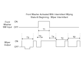
Washer activation logic with inactive front wiper:
When the front wiper is not active and if the washer signal is active for more than 200 ms and less than 600 ms, the following sequence is started:
T2 second (0.3 second) after the washer is switched on, the front wiper signal is switched on with the current level speed
T3 second (700 ms) the front wiper signal is switched off
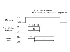
T2 = 0.3 s.
T3 : 0.7 s.
Washer activation logic with inactive front wiper:
When the front wiper is not active and if the washer signal is active for more than T1=0.6 seconds, the following sequence is started:
T2 second (0.3 second) after the washer is switched on, the front wiper signal is switched on with the current level speed
T3 second (2.7 ~ 3.3 seconds) after the washer is switched off, the front wiper signal is switched off
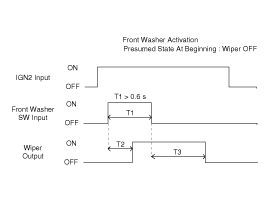
T2 = 0.3 s.
T3 : 2.7 ~ 3.3 s.
Description
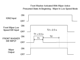
Washer activation logic with active front wiper:
When the front wiper is active, the current speed of the front wiper is kept during 0.3 sec of the washer signal and after T3 seconds (wiper activation due to washer) the front wiper returns to the wiping speed requested by the switch or the rain sensor. Depending on the mode of wiper that is active, the wiping action linked to the washer has to be stopped or not.
Here are the following wiper modes and the actions:
Wiper mode before the washer is switched ON (with or without rain sensor) | Wiper Speed During Washing |
Off | Low |
Intermittent | Low |
Low Speed | Low |
High Speed | High |
T1 > 60 ms, T2 : period of intermittence, T3 : 0.3 sec, T4 : 2.5 ~ 3.8 sec
Interaction with ignition key position & park switch
Interaction with Ignition key position:
Front wiper and washer functions are active when the ignition key is in run position.
In the start state, all the wiper and washer outputs are halted (in order to have the maximum power for the start of engine).
In the off and ACC states, the front wiper and washer are not activated.
Interaction with Ignition Key position:
If the ignition key leaves the run position while wiper operation, the wiper stops at the current position and will move to the park position the next time ignition key is run.
Start / stop of wiping:
When Front Wiper Ctrl CAN signal is received with:
LOW value, the output Front Wiper on/off is set to on and the output Front Wiper low/high is set to low
HIGH value, the output Front Wiper on/off is set to on and the output Front Wiper Low/High is set to high
off value, the output Front Wiper on/off is set to off
Interaction with the park switch:
When the Front Wiper Ctrl CAN signal has off value and the front wiper is not parked, if the IGN2_INPUT signal goes to on, then the output signal Front Wiper on/off is set to on and Front Wiper Low/High is not changed.
Interaction with the park switch:
When the IGN2 input signal is already on, if the Front Wiper Ctrl CAN signal has OFF value and the front wiper becomes not parked, then the output Front Wiper on/off signal is not changed.
The vehicle is equipped with a Rear Wiper and Washer, locally controlled (manual operation) by a Rear MF switch (RMS) connected to the IPM module. This functionality is directly accessible to the driver. It consists in the possibility to activate or deactivate the wiper of the rear glass. When the driver decides to activate the rear wiper, he has to choose between several modes of operation using the rear MF switch (RMS):
Continuous low speed
Rear washer switch
The rear wiper uses a bi-directional motor with integrated logic for rotation sense change, the RAM module manages the wiping period (intermittent or low speed) and park operation.
Another switch is also used for the rear washer. It consists in activating the front washer pump, located under hood and connected to the FAM module. The rear washer activation has a consequence on the activation of the rear wiper in order to clean the rear glass.
The driver can be informed of the low level of washer fluid by an indication on the cluster panel.
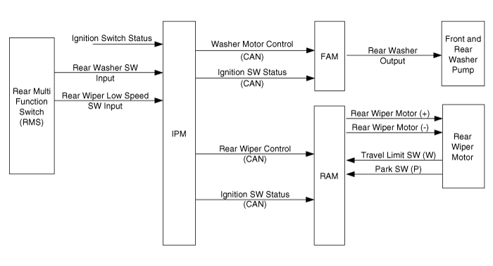
Rear wiper activation logic :
If the Rear Wiper Low Speed Sw is ON, then the CAN signal Rear Wiper Ctrl is sent with following logic:
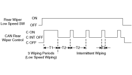
+/-10% T1 = 6.2 sec, T2 = 6 sec, T3 = 700 ms
The vehicle is equipped with a Defogger function, locally controlled (manual operation) by a windshield and rear defogger switches.
This function controls the heating defogger grids on windshield, rear glass, and rear view mirrors (managed by DDM and ADM).
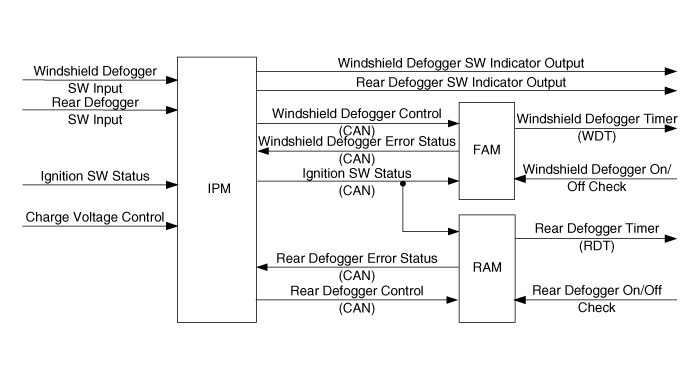
The defogger of rear view mirrors managed by DDM and ADM modules is not shown on this diagram,
as it uses the same Rear Defogger control CAN signal as the RAM module.
Open Fuel Door switch on DDM drives the solenoid for the Fuel Filler Door opening.
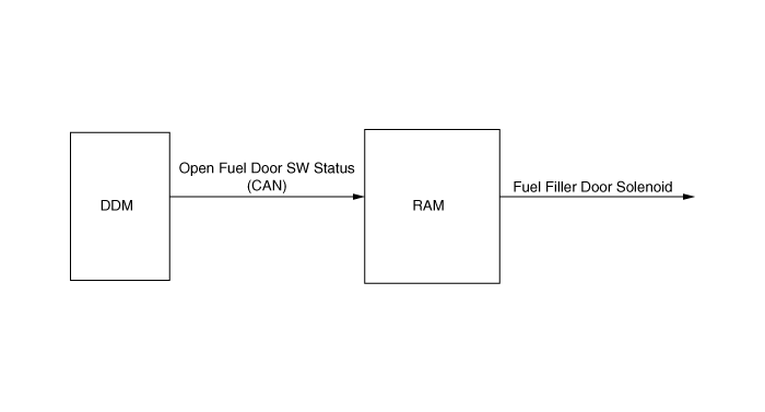
Fuel filler door solenoid definition:
In case of closed → open transition of Open Fuel Door Sw Sts, Fuel filler door solenoid output is set to on while pushing the switch (Max. 10sec) then off.
During or after this pulse, in case of open → closed transition of Open Fuel Door Sw Sts, there is no influence on the Fuel filler door solenoid output.
Time between 2 pulse commands:
A new CAN signal Open Fuel Door Sw Sts is received with open value within 1.5s after first message will not be taken into account.
This function defines the conditions for allowing use of power windows after that the ignition key has been removed from the key cylinder.
Each rear door is equipped with a power window.
The RAM module manages power window motors and switches, but controls neither the window position nor the motor current. RAM does not implement any stall mechanism detection.
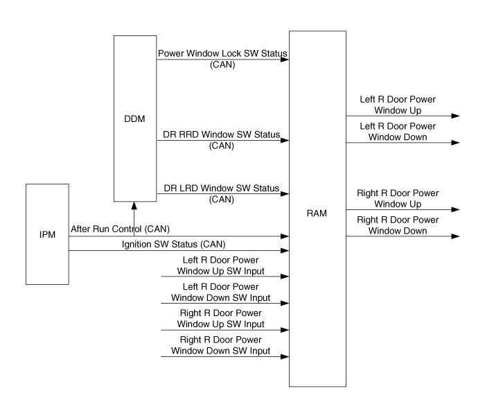
Rear doors window control:
When a power window switch is pressed, the corresponding motor output is ON until the switch is released and no more than 10+/- 1sec
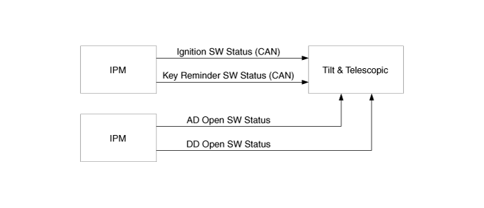
Tilt and Telescopic function provides a motorized steering wheel position adjustment. This equipment comes with the IMS option.
The Tilt &Telescopic CAN unit uses the ignition key position managed by the IPM.
IGN2 switch and the RH/LH seat warmer switches control the Rear Seat Warmer relays.
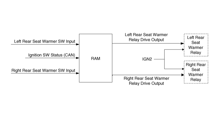
Left and right rear seat warmers working condition:
The left and right rear seat warmers can be activated only if ignition key is in RUN position (Ignition Sw Sts CAN signal is received with RUN value). When the rear seat warmers (left/right) are activated and the ignition key leaves the RUN position, the rear seat warmers are stopped.
Left rear seat warmer operation:
At each OFF → ON transition detected on left rear seat warmer switch input, the left rear seat warmer relay drive output signal toggles its state.
Right rear seat warmer operation:
At each off → on transition detected on right rear seat warmer switch input, the right rear seat warmer relay drive output signal toggles its state.
Adjust Pedal allows to activate Adjustable Pedal feature; IPM needs to control the power source (by relay coil control) of the adjustable Pedal switch unit.
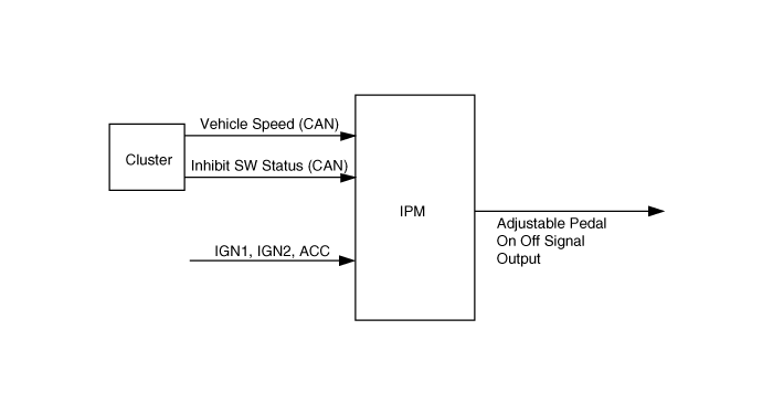
Adjustable Pedal
N° | Inhibit SW Status | Vehicle Speed | Ignition SW Status | Adjustable Pedal On Off Signal Output |
1 | P | 0 kph | Run | On |
2 | x | x | Off, Acc | On |
3 | P | 1-254 kph | Run, Start | Off |
4 | Not P | x | Run, Start | Off |
x = any value
This function provides assistance in tailgate latching and cinching. The RAM sends a command to external module, connected to latching and cinching motors.
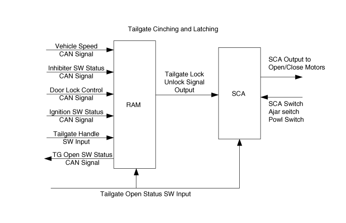
Tailgate cinching and latching 30 s enable timer (1):
The tailgate cinching and latching function is enabled for 30 sec after receiving the Door Lock Ctrl CAN signal with tailgate unlock value. During this delay, the tailgate can be opened if the Inhibit Sw Sts CAN signal is received with P or N values and if the vehicle speed is ≤ 5 km/h.
During the 30 sec Cinch & Latch Timer delay:
If the tailgate close → open transition is detected during this 30 sec delay, the timer is stopped and the function becomes disabled immediately.
After this 30 sec Cinch & Latch Timer delay:
After this 30 sec delay, if no action is detected on the tailgate handle switch, the cinching and latching function is disabled (any action on tailgate handle switch is ignored).
1) This timer is not started when the vehicle state is unlocked, i.e. after successful completion of the key reminder unlock sequence or if the previous value of Door Lock Ctrl was : all unlock, rear door and tailgate unlock, rear door, tailgate and driver door unlock, rear door, tailgate and assist door unlock.
Cinching and latching function initial state after the cold reset:
After the cold reset the initial state of tailgate cinching and latching function (enabled / disabled) depends on the rear doors lock monitoring switch state:
R RD Lock Monitoring SW Input | L RD Lock Monitoring SW Input | Tailgate cinching and latching function state |
On | Off | Enabled (1) |
Off | On | |
On | On | |
Off | Off | Disabled |
(1) Only if the Inhibit Sw Sts CAN signal is received with P or N values and if the vehicle speed is ≤ 5 km/h
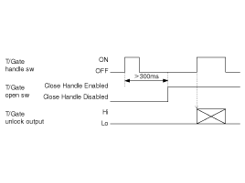
Tailgate unlock logic for latch pulse generation:
→ Case 1
→ Case 2
→ Case 3
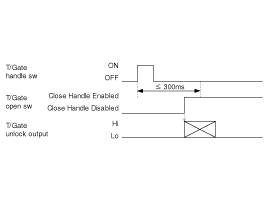
→ Case 4
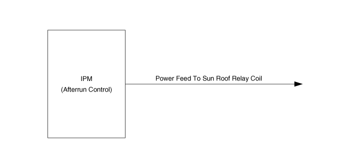
This function controlled by the IPM defines the condition for switching on or off power feed to Sun Roof Relay Coil.
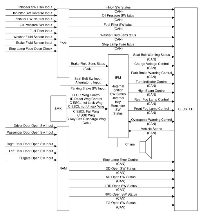
The cluster indicators, managed by the cluster module, show the state of activated functions or warn the driver if a problem occurs. Some visual cluster indications are associated with a chime warning.
The IPM, FAM or RAM sends on the CAN the status of several switches and sensors. The cluster module receives the status of several switches and sensors from the CAN and activates the corresponding indicators.
The following table gives a list of existing cluster indicators and associated chime warnings:
Cluster Indicator | Associated Chime Warning | Description |
Oil Pressure | - | This function warns the driver if the oil pressure becomes low. The FAM receives on a digital input the status of oil pressure switch and sends it on the CAN |
Sediment Fuel Filter* | - | This function indicates that the fuel filter needs to be replaced. The FAM receives on a digital input the status of the fuel filter and sends it on the CAN |
Brake Fluid | - | This function warns the driver if the brake fluid level becomes low. The FAM receives on a digital input the status of the brake fluid sensor and sends it on the CAN |
Washer Fluid | - | This function warns the driver if the washer fluid level becomes low. The FAM receives on a digital input the status of the washer fluid sensor and sends it on the CAN |
Seat Belt | Seat Belt Warning | This function warns the driver if the seat belt is not attached. The IPM receives on a digital input the status of seat belt switch and sends it on the CAN.The IPM activates also an associated chime warning. |
Park Brake | Park Brake Warning | This function indicates that the park brake is activated. The IPM sends the parking brake warning on the CAN. This signal is based on following information: The status of the parking brake switch. The vehicle speed The brake fluid status. The IPM activates also an associated chime warning. |
Charging Voltage | - | This function signals the low charging voltage level. The IPM receives on analog input the voltage of alternator L and sends a warning when the voltage is low on the CAN |
Turn Indicators | - | This function signals that one of turn indicators is activated. The cluster module uses the Turn Indicator Ctrl CAN signal generated by IPM |
High Beam | - | This function signals that the high beam lamps are activated. The cluster module uses the High Beam Ctrl CAN signal generated by IPM |
Front Fog | - | This function signals that the front fog lamps are activated. The cluster module uses the Front Fog Lamp Ctrl CAN signal generated by IPM |
Door Open | Doors open Warning | There are 4 individual door open indicators on the CLU, such as driver door open switch indicator, passenger door open indicator, rear left door open indicator and rear right door open. The RAM receives on digital inputs the status of door open switch and sends it on the CAN. The IPM activates an associated chime warning. |
Tailgate Open | Tailgate open Warning | This function indicates that the tailgate is opened. The RAM receives on digital inputs the status of tailgate open switch and sends it on the CAN. The IPM activates an associated chime warning. |
The chime control function provides also the several chime warnings that are not associated with the cluster visual indications.
The following table gives a list of these warnings:
Chime Warning | Description |
Over Speed Warning | The IPM receives the over speed warning by the CAN |
Key Reminder Warning | This warning is based on the following information:The status of ignition key, from digital input. The status of the driver door, from CAN |
Light Warning | This warning is based on the following information: The status of the driver door, from CAN. The light state of park and tail lamps, from digital inputs (MF switch) |
All following SMK warnings are activated by IPM when receiving CAN signals from the SMK ECU.
SMK Chime warning | Description |
ID Out Warning | Activated when a valid fob is not inside the vehicle, all doors are closed and ignition not off |
Deactivation of IDs warning | Activated when a valid fob is inside the vehicle and alarm is in arm state |
Escl not locked warning | Activated when all terminals are off and the Escl is not locked with a lock command |
Escl not unlocked warning | Activated when all terminals are off and the Escl is not unlocked with an unlock command |
Escl ecu fail warning | Activated when all terminals are off and a Escl failure is detected |
SSB button warning | Activated when all terminals are off and a SSB failure is detected |
Key battery discharging warning | Activated if key battery is low |
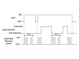
Seat Belt Warning Chime and Indicator synchronization:
When the Seat Belt Warning Chime is activated, the Seat Belt Indicator is blinking simultaneously.
Seat Belt Warning indicator :
The seat belt warning indicator (Seat Belt Warning Sts) can be lighted only when the ignition switch is in run or start position
Seat Belt Warning indicator :
If the Ignition Sw Sts is RUN or START when the Seat Belt Sw Input is fastened, the seat belt warning indicator (Seat Belt Warning Sts) is blinking for 6 seconds at 50% duty in 1.0 second
Seat Belt Warning indicator :
When Seat Belt Sw Input is not fastened, the seat belt warning indicator (Seat Belt Warning Sts) is blinking for 6 seconds at 50% duty in 1.0 second.
Seat Belt Warning indicator :
If the Seat Belt Sw Input is fastened during the 6 seconds, the seat belt warning indicator (Seat Belt Warning Sts) is blinking till the end of the 6 seconds
Seat Belt Warning chime :
The seat belt chime warning can be activated only when the ignition switch is in run or start position
Seat Belt Warning chime :
The chime is activated during 6 second when the seat belt is not fastened.
The chime will stop immediately if the seat belt is fastened during the 6 seconds of the chime.
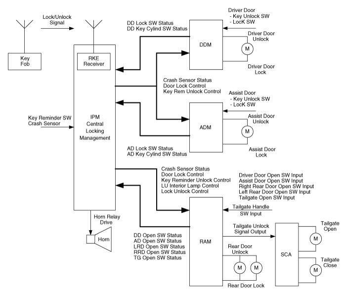
Central locking/unlocking logic is controlled by IPM. Locking/Unlocking inputs are located in ADM, DDM (Lock/Unlock switch, door knobs, door key cylinder) and in IPM (RKE receiver).
Locking/Unlocking actuators are located in ADM for assist door, DDM for driver door and RAM for rear doors and tailgate.
There are 5 ways of operating central lock/unlock:
With Key fob
With Smart key ECU (when equipped)
With Door Lock/Unlock switches located on ADM/DDM (assist/driver door trim).
With Door Key Cylinder Lock/Unlock switches located on assist/driver door.
Treatment for those switches depends on the country.
RAM/ADM/DDM Input Control
Except for RKE, all inputs for controlling lock/unlock actions are located on ADM, DDM or RAM.
ADM/DDM/RAM controls those inputs and manages the configuration according to the country. IPM controls central lock/unlock process.
If a lock/unlock command is issued by ADM/DDM to IPM through CAN, IPM does not check the command validity according to the country.
Door Lock Monitoring Switches
Door Lock Monitoring Switches are equipped on all vehicles. ADM/DDM send Assist door Lock Monitor Switch status/Driver door lock monitor switch status to IPM with value locked when the corresponding Door Monitoring Switch indicates a locked door and unlocked otherwise.
RAM sends rear right door Lock Monitor switch status/rear left door lock monitor switch status to IPM with “Locked” value when the right/left rear doors are locked, otherwise witH “Unlocked” value.
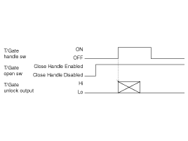
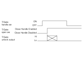
Concerning Tailgate Open Switch status is closed handle disabled when it is closed and locked and closed handle enabled when it is closed and unlocked
Door Key Cylinder
When Assist/Driver Door Key Cylinder request lock/unlock, ADM/DDM send assist door Key Cylinder Sw Sts/ Driver door Key Cylinder Sw Sts CAN signal with value lock/unlock.
Door Lock Switches
When Assist/Driver Door Lock Switch request lock, ADM/DDM send Assist door lock switch status /Driver door lock switch status CAN signal with value lock.
When Assist/Driver Door Lock Switch request unlock, ADM/DDM send Assist door lock switch status /Driver door lock switch status CAN signal with value unlock.
ADM/DDM Actuators Control
ADM and DDM control lock/unlock motors.
DDM
LOCK/UNLOCK is performed when DDM receives Door Lock Ctrl CAN signal from IPM
ADM
LOCK/UNLOCK is performed when ADM receives Door Lock Ctrl CAN signal from IPM
Lock/unlock with Door Lock Switch does not depend on Ignition Key position.
Working conditions
For vehicle not equipped with burglar alarm :
All following requirements are applicable.
For vehicle equipped with burglar alarm :
In ARM alarm state, there is no action on door lock switch. So, all following requirements are applicable in alarm state disarm, prearm, 30sec delay, arm wait, alarm, after alarm and rearm.
Lock
Locking process
Upon a transition of Assist door lock switch status or Driver door lock switch status CAN signal from any value to lock value, IPM issues Door Lock Ctrl CAN signal with value lock all for 500 ms.
Unlock
Unlocking process
Upon a transition of Assist door lock switch status or Driver door lock switch status CAN signal from any value to unlock value, IPM issues Door Lock Ctrl CAN signal with value unlock all for 500 ms.
Unlocking process
When Assist door lock switch status and Driver door lock switch status CAN signal state change at the same moment, IPM uses Driver door lock switch status state for lock/unlock operation
This locking/unlocking process doesn’t depend on the Driver Door Open Switch status, Assist Door Open Switch status, Rear Doors Open Switch status Tailgate Open Switch Status.
This locking/unlocking process doesn’t activate or deactivate hazard lamps, horn or interior lamps.
Fast lock / unlock
If IPM receives door lock/unlock command again while lock/unlock pulse (500ms) is ongoing, lock/unlock pulse is stopped immediately and new lock/unlock pulse is sent after 100ms time delay.
When a lock/unlock command is requested using Assist/Driver door key cylinder, ADM/DDM modules deal with this request according to §0 and use CAN signal to issue the command to IPM, then IPM issues central lock/unlock when Assist/driver door lock monitoring switches is locked/unlocked.
When IPM issues lock/unlock command, it does not check monitoring switches to make sure command was successful.
When the key is withdrawn from Ignition Key Cylinder if any door is locked, the IPM issues a command to unlock only locked doors.
The purpose of this function is to avoid locking the doors when the key is inserted in the Ignition Key Cylinder and the vehicle speed is lower than 3 km/h.
Requirements for SMK only
There is no insertion of ignition key with SMK equipment, all following requirements are applicable for SMK equipment with these changes :
“key is inserted” must be replaced by CAN signal Key Reminder Sw Sts is set to value inserted
“key is not inserted, key is removed” must be replaced by CAN signal Key Reminder Sw Sts is set to value not inserted
If a SMK reminder unlock is on going, a Key reminder unlock is not taken into account.
Key reminder unlock working condition
The key reminder function is active when key is inserted in the ignition key.
Key reminder unlock for driver door lock change
When ignition key is inserted into the ignition key cylinder, driver door is open and driver door lock monitoring sw status changes from unlocked to locked, then Key Reminder Unlock Ctrl signal is sent with value DD long unlock (consisting in 1s +/-0.1s long driver door unlock)
Key reminder unlock, no interruption
The long unlock cannot be interrupted by any action (key removed, door closed…)
Key reminder unlock, second unlock
If driver or assist door remains locked after the 1s long unlock and if driver or assist door is still OPEN And key is still inserted, then Key Reminder Unlock Ctrl signal is sent with values no value/short unlock at a rate of 0.5s/0.5s three times.
Key reminder unlock, interruption
The short unlock sequence is interrupted (after the current unlock has ended) if DD/AD Lock Monitoing Sw Sts is set to unlock, key is withdrawn from key cylinder or DD/AD Open Sw Sts is set to closed
Key reminder unlock, door closing
When closing driver/assist door within 0.5 second after locking this door, Key Reminder Unlock Ctrl signal with long unlock value is sent
Key reminder unlock, door locking
When locking driver/assist door within 0.5 second after closing this door, Key Reminder Unlock Ctrl signal with long unlock value is sent
Key reminder unlock, driver door opened when locked
If driver door is close to open when key reminder switch is IN and driver’s door locked, then issue short unlock pulse for 0.5 sec.
Key reminder unlock, assist door opened when locked
If assist door is close to open when key reminder switch is IN and assist’s door locked, then issue short unlock pulse for 0.5 sec.
Key reminder unlock, key removed
When ignition key is removed within 0.5 second after pressing driver/assist door lock switch, key reminder function is cancelled (Key Reminder Unlock Ctrl at no action) and central door lock is issued.
Key reminder unlock pattern
After issuing 4 successive unlock output, the reset condition for “Key reminder unlock function” is as follow :
Door open switch is Open to Close (In this case, issue one time unlock pulse for 0.5sec and then go to initial)
Key reminder switch is IN to OUT (No unlock output and go to initial mode)
Knob switch is Lock to Unlock (No unlock output and go to initial mode)
Key reminder unlock while inserting key
When inserting a key into ignition key cylinder with door opened and locked, only LONG_UNLOCK unlock is issued (no short unlock).
Key Reminder Unlock
When CAN signal Key Reminder Unlock Ctrl is received with Short Unlock,
Door Unlock is sent with value ON during 0.5s to right and left rear doors
Key Reminder Unlock
When CAN signal Key Reminder Unlock Ctrl is received with Long Unlock,
Door Unlock is sent with value ON during 1s to Tailgate, right and left rear doors
Key Reminder Unlock Priority
CAN signal Key Reminder Unlock Ctrl long or short unlock have higher priority than Door Lock Ctrl lock or unlock command
Key reminder unlock, tailgate unlock
When CAN signal Key Reminder Unlock Ctrl is received with Short Unlock or Long Unlock and if tailgate is closed, tailgate Open Sw Sts is set to Closed Handle Enabled
In case of crash of the vehicle, all doors must be unlocked as fast as possible.
Crash Unlock Function Activation
The crash unlock function is activated after 100 ms delay after the ignition switch state is changed from off or ACC to RUN or START position (Ign1 active).
Crash Unlock Function
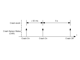
In case of crash, the time between the “Crash Sensor From Air Bag Unit” signal activation sent by the sensor and the unlock motors activation (driver door, assist door, Right/Left rear door and tailgate unlock) to unlock the doors must be less than 40 ms.
Crash Unlock Function Deactivation
The crash unlock function is deactivated when the ignition switch state is changed from run or start to ACC or off position.
There are two steps in deactivation:
crash sensor deactivation in ignition switch ACC or OFF position
turn indicators deactivation in ignition switch OFF position (sending also the Crash Sensor Sts CAN signal with off value)
Crash Unlock Function
Crash Unlock Function (initial unlock output)
When the vehicle crashes, the airbag unit activates the “Crash Sensor From Air Bag Unit” signal. IPM detects this signal change, filters it and sends the CAN signal Crash Sensor Sts with the following logic:
Crash Unlock Function
After this initial unlock output, a 100 ms long pause (Crash Sensor Sts =off) is done and then if any door is still locked, CAN signal Crash Sensor Sts = ON is sent again for 5 s.
Crash Unlock Function
This unlock action is done one more time if doors are still locked after 2 unlock attempts. After 3 attempts, if any door is still locked, IPM stops trying to unlock and Crash Sensor Sts CAN signal is set to off.
Crash Unlock Function
Once a crash has occurred, Door Lock Ctrl cannot be set to lock doors until crash is cancelled (ignition switch status turned off). Only unlock is authorised.
After Crash Unlock
When all doors are unlocked by crash unlock function, if any door becomes locked, the IPM sends the CAN signal Crash Sensor Sts = ON again for 5sec then off
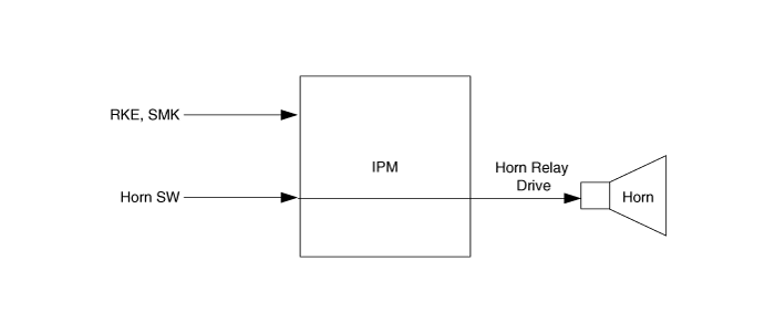
The different ways of activation of the horn are:
The driver is directly activating the horn manually. Since the horn stalk switch is directly wired to the horn relay, the software does not manage this command.
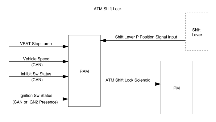
The purpose of this function is to prevent gear change from <P> to others if no pressure is applied on brake pedal.
ATM stands for Automatic Transmission
Answers back give a visual and/or sound feedback to user’s action. These actions are linked to lock / unlock action and the alarm status (if equipped). Visual feedback is realized with the hazard turn indicators and the interior lighting, sound feedback with the horn sound.
Here are the different answers back with their description.
Horn answer back sequence description
Horn lock sequence : Horn Relay Drive is set to ON for 50ms to activate the horn
SMK sound answer back sequence description (with SMK system equipped)
SMK sound lock sequence : IPM sends the CAN signal Chirp Sound Ctrl with the value ON for 500ms then OFF
Hazard answer back sequence description
Hazard lock sequence : IPM sends the CAN signal Turn Indicator Ctrl with the value all on for 1s to switch on hazard lamps then all off
Hazard unlock sequence : IPM sends the CAN signal Turn Indicator Ctrl with the sequence value all on / all off during 2s to blink the hazard lamps at 1Hz frequency (duty 50%) then all off
Interior lighting answer back sequence description
Interior lighting lock sequence : IPM sends the CAN signal Interior Lamp Ctrl with the value lock for 500ms then off
Interior lighting unlock sequence : IPM sends the CAN signal Interior Lamp Ctrl with the value unlock for 500ms then OFF
In normal mode, all modules and the CAN network are powered and running. All module functions are available; communication through the bus is possible as well as communication with the SCAN tool.
Low power mode is a state in which the modules try to lower their power consumption as much as possible in order to save energy. Low power mode can also be called “sleep mode”. In this mode, CAN bus communication is not available and the ignition key position is OFF (Acc = OFF Ign1 = OFF and Ign2 = OFF). In low power mode the normal features of the modules are not available. The modules have to switch to normal mode in order to perform their functions. Thus, in low power mode, the modules periodically monitor changes on a given set of inputs in order to detect a user request and then enter normal mode. Those monitored inputs are called “Wake Up” inputs.
Full low power is the lowest power consumption state in which all the modules inputs and outputs as well as the modules themselves are in their lowest power consumption state. This implies that none of the equipments controlled by the modules are active, i.e., they do not consume energy. For example, in full low power mode, keyhole illumination must be off. All power consumption measurements in low power mode are made in full low power mode.
Low power mode is entered to save energy when the car is not running. This implies that low power mode can only be entered when ignition key is in OFF position. In low power mode, the software is not running, hence all the modules features must be in a stable inactive state for low power mode to be entered. The exact conditions for allowing a module to enter low power mode depending on each function are described in requirements.
In order to enter low power mode, the K line transceiver must be powered down. This means that low power mode cannot be entered while the SCAN tool is connected.
Sequence for entering low power mode for one module is as follows:
Check that all the module functions are in a state where they can enter low power mode.
If all the module functions are in a state where they can enter low power mode for 10s, the module sends a CAN message informing that it is ready to enter low power mode.
When all the modules on the network are ready to enter low power mode, the IPM sends a CAN message authorizing the CAN to be shut down.
Once the CAN network is in low power mode, each module enters low power mode.
This process can be interrupted at any time to go back to normal mode when a wake up event is detected.
The transition process from normal to low power mode is the same whether full low power or intermediate low power mode is being entered.
Normal mode has to be entered from low power mode when changes on one or several inputs create a condition where one of the modules features must be activated. Since the modules cannot process the inputs in low power mode, they must enter normal mode to process the inputs and activate the requested feature.
In low power mode, the inputs that have an effect on the features active when ignition key position is OFF are monitored periodically in order to detect a valid “wake up” condition. Those inputs are called “wake up” inputs. They include several switches, Ign2, Ign1, Acc but also K line and CAN messages and a valid RKE signal.
In order to avoid false transitions to normal mode due to noise, wake up inputs are debounced before transition from low power to normal mode takes place.
Intermediate low power is a state in which the modules lower their power consumption as much as possible. In this mode, one or several components connected to the modules are active. The modules reduce their power consumption but cannot achieve full low power mode because of those external components that need to be maintained in powered state.
Safe mode
There are 2 safe modes:
Software safe mode;
Hardware safe mode.
The software safe mode is a transition state entered as soon as one of the CAN signals monitored is lost. It is built in such a manner that the current state of the lighting on the low beams and tail lamps is kept. The rest of the functions follow their own default behavior.
This transition state is mainly used to avoid going back and forth between the normal mode and the rescue mode in case of sporadic trouble on a signal. This will avoid having the low beams and tail lamps being turned on/off for small periods.
The hardware safe mode consists in maintaining the state of the low beam if the exterior lighting was active before entering the safe mode.
The goal of this mode is to be able to cope with failures that may happen on some of the most critical functionalities (for the driver security) of the system.
There are 2 rescue modes:
The hardware rescue mode;
The software rescue mode.
The software rescue mode consists in activating some safety functions when IGN2 input = ON:
Switch on the low beams (FAM), park lamps (FAM), tail lamps (RAM) and cluster backlighting (IPM);
Unlock of all the doors when the rescue mode is entered with IGN2 input = ON
All other functions (apart from head lamp low beams, tail lamps and front wipers) will try to behave as specified and will enter their own default mode if it is not possible.
Front wipers do not need to be turned on by software in rescue mode because wipers can be turned on by manually setting the MF switch to low speed. The FAM software must keep the same state as before entering the rescue mode.
When IGN2 input = OFF, low beams, park/tail lamps and cluster backlighting are turned off.
The hardware rescue mode will switch on the low beams and the tail lamps. The front wipers are not taken into account due to the direct wiring of the stalk switch (low speed position).
The boards are designed to allow this hardware rescue mode to ensure their own integrity.
Note that none of the modules powered by IPM, RAM or FAM are kept powered in rescue mode.