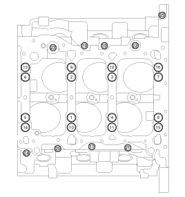
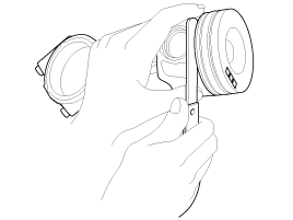
5.
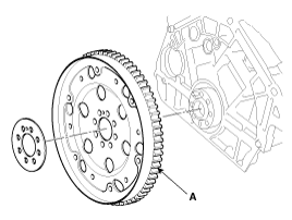
Remove the drive plate(A).
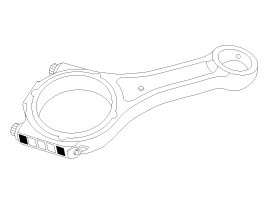
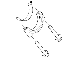
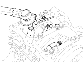
Remove the connecting rod caps.
Mark the connecting rod caps to be able to reassemble in the original position and direction.
Remove the piston and connecting rod assembly.
Using a ridge reamer, remove all the carbon from the top of the cylinder.
Push the piston, connecting rod assembly and upper bearing out of the cylinder block.
Keep the connecting rod and the cap with its bearings together.
Arrange the piston and connecting rod assemblies in the correct order.
Remove the piston and conecting rod assembly. Using a press machine, remove the piston pin from the piston.
Remove the piston rings.
Arrange the piston rings in its order, having an eye to the 'Y' mark on the ring which tells you it is the upper side.
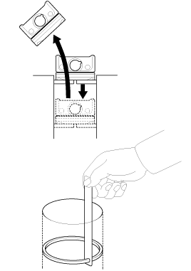
Remove the drive plate(A).
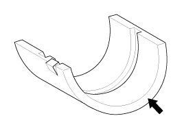
Remove the bedplate.
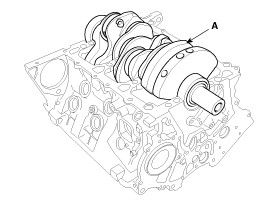
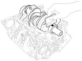
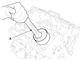
Lift the crankshaft(A) out of the block, being careful not to damage journals.
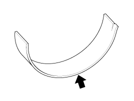
Arrange the main bearings and thrust bearings in the correct order.
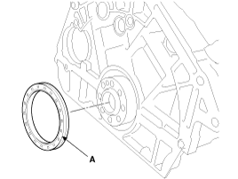
Remove the rear oil seal(A).
Remove the oil jet(A).
Check the connecting rod bearing oil clearance.
Check the marks on the connecting rod and rod cap for accurate reassembling.
Loosen the two connecting rod cap bolts.
Remove the connecting rod cap and the lower bearing.
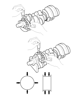
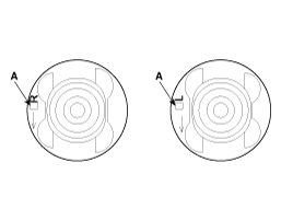
Clean up the crankshaft pin journal and its bearings.
Put on the plastigage along the axis direction of the crankshaft.
Reassemlbe the lower bearings and the connecting rod caps and tighten the bolts with the specified torque below.
Tightening torque :
27.5 ~ 31.4Nm (2.8 ~ 3.2kgf.m, 20.3 ~ 23.1lb-ft) + 88˚~92˚
Do not rotate the crankshaft.
Do not reuse the connecting rod cap bolts.
Remove the connecting rod cap again.
Measure the plastigage at its widest point.
Crankshaft pin outer diameter identification mark | Connecting rod big end inner diameter identification mark | Assembling classification of upper bearings(identification mark) | Oil cleareance(mm(in.))(reference value) |
A | A | Red | 0.024~0.050(0.0009~0.0020) |
B | Red | 0.030~0.056(0.0012~0.0022) | |
C | Yellow | 0.026~0.052(0.0010~0.0020) | |
B | A | Red | 0.030~0.056(0.0012~0.0022) |
B | Yellow | 0.026~0.052(0.0010~0.0020) | |
C | Yellow | 0.032~0.058(0.0013~0.0023) | |
C | A | Yellow | 0.026~0.052(0.0010~0.0020) |
B | Yellow | 0.032~0.058(0.0013~0.0023) | |
C | Blue | 0.028~0.054(0.0011~0.0021) |
If the measurement from the plastigage is out of the specification, change the bearings with new ones of the same identification color. Recheck the oil clearance.
Do not file, shim, or scrape the bearings or the caps to adjust the clearance.
If the plastigage shows the clearance is still incorrect, try the larger or smaller bearing. Recheck the oil clearance.
If the proper clearance still cannot be obtained after using the appropriate larger or smaller bearings, replace the crankshaft and restart measuring.
If the marks are indecipherable because of an accumulation of dirt or dust, do not scrub them with a wire brush or scraper. Clean them only with solvent or detergent.
Mark | Connecting rod big-end inner diameter |
A | 66.500 ~ 66.506 mm(2.6181~2.6183 in.) |
B | 66.506 ~ 66.512 mm(2.6183~2.6186 in.) |
C | 66.512 ~ 66.518 mm(2.6186~2.6188 in.) |
Mark | Crankshaft pin journal outer diameter |
A | 63.494 ~ 63.500 mm(2.4998~2.5000 in.) |
B | 63.488 ~ 63.494 mm(2.4995~2.4998 in.) |
C | 63.482 ~ 63.488 mm(2.4993~2.4995 in.) |
Size code | Color | Connecting rod upper bearing thickness |
A | Blue | 1.497 ~ 1.507mm (0.0589 ~ 0.0593in.) |
B | Yellow | 1.487 ~ 1.497mm (0.0585 ~ 0.0589in.) |
C | Red | 1.477 ~ 1.487mm (0.0581 ~ 0.0585in.) |
Color | Connecting rod lower bearing thickness |
- | 1.485 ~ 1.489mm (0.0585 ~ 0.0586in.) |
Select the suitable bearing by using the selection table below.
Connecting rod bearing | Connecting rod mark | |||
A | B | C | ||
Crankshaft pin journal mark | A | Red | Red | Yellow |
B | Red | Yellow | Yellow | |
C | Yellow | Yellow | Blue | |
Check the connecting rods.
When reinstalling, make sure that cylinder numbers put on the connecting rod and cap at disassembly match. When a new connecting rod is installed, make sure that the notches for holding the bearing in place are on the same side.
Replace the connecting rod if it is damaged on the thrust faces at either end. Also if step wear or a severely rough surface of the inside diameter of the small end is apparent, the rod must be replaced as well.
Using a connecting rod aligning tool, check the rod for bend and twist. If the measured value is close to the repair limit, correct the rod by a press. Any connecting rod that has been severely bent or distorted should be replaced.
Check the crankshaft bearing oil clearance.
To check main bearing-to-journal oil clearance, remove the bed plate and lower bearings.
Clean each main journal and lower bearing with a clean shop towel.
Place one strip of plastigage across each main journal.
Reinstall the lower bearings and bed plate, then tighten the bolts.
Reinstall the lower bearings and bed plate, then tighten the bolts.
If the bedlpate bolts are damaged or deformed, replace them with new ones.
Tighten the No.18, 20, 21 bolts in its number order(18→20→21) with the specified torque.
Tightening torque :
29.4 ~ 33.3Nm (3.0 ~ 3.4kgf.m, 21.7 ~ 24.6lb-ft)
Tighten the No.1~16 bolts in two steps with the specified torque and angle below.
Tightening torque :
61.8 ~ 65.7Nm (6.3 ~ 6.7kgf.m, 45.6 ~ 48.5lb-ft) - 1st step
120° ~ 124° - 2nd step
Loosen the bolts No. 18, 20 and 21.
Tighten the No.17~25 bolts with the specified torque below.
Tightening torque :
29.4 ~ 33.3Nm (3.0 ~ 3.4kgf.m, 21.7 ~ 24.6lb-ft) - 1st step
Do not rotate the crankshaft.
Remove the bed plate and lower bearing again, and measure the widest part of the plastigage.
Standard oil clearance :
0.030 ~ 0.048mm (0.0012 ~ 0.0019in)
If the plastigage measurement is too wide or too narrow, remove the bearings and then install a new bearings with the same color mark. Recheck the oil clearance.
Do not file, shim, or scrape the bearings or the caps to adjust clearance.
If the plastigage shows the clearance is still incorrect, try the larger or smaller bearing. Recheck the oil clearance.
If the proper clearance cannot be obtained by using the appropriate larger or smaller bearings, replace the crankshaft and start the measurement from the first.
If the marks are indecipherable because of an accumulation of dirt and dust, do not scrub them with a wire brush or scraper. Clean them only with solvent or detergent.
Mark | Cylinder block journal bore inner diameter |
A | 80.000 ~ 80.006 mm(3.1496~3.1498 in.) |
B | 80.006 ~ 80.012 mm(3.1498~3.1501 in.) |
C | 80.012 ~ 80.018 mm(3.1501~3.1503 in.) |
Mark | Crankshaft main journal outer diameter |
A | 75.994 ~ 76.000 mm(2.9919~2.9921 in.) |
B | 75.988 ~ 75.994 mm(2.9916~2.9919 in.) |
C | 75.982 ~ 75.988 mm(2.9914~2.9916 in.) |
Size code | Color | Crankshaft bearing thickness |
A | Red | 1.994 ~ 1.997mm (0.0785 ~ 0.0786in.) |
B | Blue | 1.991 ~ 1.994mm (0.0784 ~ 0.0785in.) |
C | - | 1.988 ~ 1.991mm (0.0783 ~ 0.0784in.) |
D | Yellow | 1.985 ~ 1.988mm (0.0781 ~ 0.0783in.) |
E | Green | 1.982 ~ 1.985mm (0.0780 ~ 0.0781in.) |
Select the suitable bearing by using the selection table below.
Crankshaft main bearing | Crankshaft bore mark | |||
A | B | C | ||
Crankshaft main journal mark | A | Green | Yellow | - |
B | Yellow | - | Blue | |
C | - | Blue | Red | |
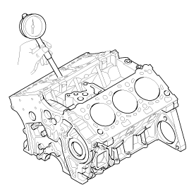
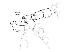
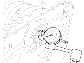
Check the crankshaft end play. Using a dial indicator, measure the clearance while prying the crankshaft back and forth.
End play
Standard : 0.1 ~ 0.3mm (0.0039 ~ 0.118in)
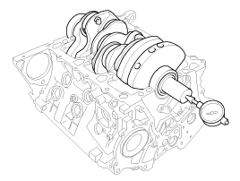
Inspect the crankshaft main journals and pin journals. Using a micrometer, measure the diameter of each main journal and pin journal.
Main journal diameter :
75.982 ~ 76.000mm (2.9914 ~ 2.9921in)
Pin journal diameter :
63.482 ~ 63.500mm (2.4993 ~ 2.5000in)
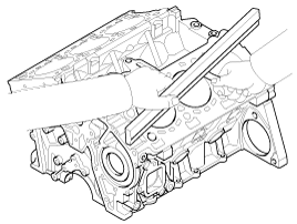
Remove the gasket material. Using a gasket scraper, remove all the gasket material from the top surface of the cylinder block.
Clean the cylinder block Using a soft brush and solvent, thoroughly clean the cylinder block.
Inspect the top surface of cylinder block for flatness. Using a precision straight edge and feeler gauge, measure the surface contacting the cylinder head gasket for warpage.
Flatness of cylinder block gasket surface
Less than 0.05mm (0.0020in)
Less than 0.042mm (0.0017in) for width
Less than 0.096mm (0.0038in) for length
Less than 0.012mm (0.0005in) for 50mm × 50mm
Inspect the cylinder bore. Visually check the cylinder for vertical scratchs. If deep scratchs are present, replace the cylinder block.
Inspect the cylinder bore diameter. Using a cylinder bore gauge, measure the cylinder bore diameter at position in a thrust and an axial direction.
Standard diameter :
84.000 ~ 84.030mm (3.3071 ~ 3.3083in)
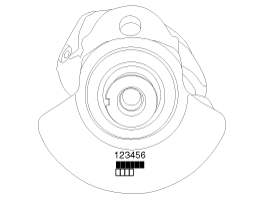
Check the cylinder bore size code on the cylinder block side face.
Mark | Cylinder bore inner diameter |
A | 84.000 ~ 84.010 mm(3.3071~3.3075 in.) |
B | 84.010 ~ 84.020 mm(3.3075~3.3079 in.) |
C | 84.020 ~ 84.030 mm(3.3079~3.3083 in.) |
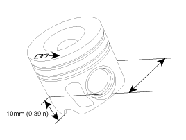
Check the piston size mark(A) on the piston top face.
Mark | Piston outer diameter |
A | 83.926 ~ 83.936 mm(3.3042~3.3046 in.) |
B | 83.936 ~ 83.946 mm(3.3046~3.3050 in.) |
C | 83.946 ~ 83.956 mm(3.3050~3.3053 in.) |
Select the piston related to cylinder bore class.
Piston-to-cylinder clearance :
0.064 ~ 0.084mm (0.0025 ~ 0.0033in.)
Oversize pistons should be selected according to the largest cylinder bore.
The size mark of piston is stamped on the top surface of the piston.
Measure the outer diameter of the piston to be used.
According to the measured outer diameter, calculate the new bore size.
New bore size = piston O.D + 0.064 ~ 0.084mm (0.0025 ~ 0.0033in)(clearance between piston and cylinder) - 0.01mm (0.0004in) (honing margin.)
Bore each of the cylinders to the calculated size.
To prevent distortion that may result from temperature rise during honing, bore the cylinder holes in the firing order.
Hone the cylinders, finishing them to the proper dimension (piston outside diameter + gap with cylinder).
Check the clearance between the piston and cylinder.
Piston-to-cylinder clearance :
0.064 ~ 0.084mm (0.0025 ~ 0.0033in.)
When boring the cylinders, finish all of the cylinders to the same oversize. Do not bore only one cylinder to the oversize.
Clean the piston.
Using a gasket scraper, remove carbon from the piston top.
Using a groove cleaning tool or a broken ring, clean the piston ring grooves.
Using a brush with solvent, thoroughly clean the piston.
Do not use a wire brush.
The standard measurement of the piston outer diameter is taken 10mm (0.39in) height from bottom land of the piston.
Standard diameter :
83.926 ~ 83.956mm (3.3042 ~ 3.3053in.)
Calculate the difference between the cylinder bore inner diameter and the piston outer diameter.
Piston-to-cylinder clearance :
0.064 ~ 0.084mm (0.0025 ~ 0.0033in.)
Inspect the piston ring side clearance. Using a feeler gauge, measure the clearance between new piston ring and the wall of ring groove.
Piston ring side clearance
No.1: 0.102 ~ 0.146mm (0.0040 ~ 0.0057in.)
No.2: 0.08 ~ 0.12mm (0.0031 ~ 0.0047in.)
Oil ring: 0.03 ~ 0.07mm (0.0012 ~ 0.0028in.)
If the clearance is out of the specification above, replace the piston.
Inspect the piston ring end gap. To measure the piston ring end gap, insert a piston ring into the cylinder bore.
Position the ring at right angles to the cylinder wall by gently pressing it down with a piston. Measure the gap with a feeler gauge. If the gap exceeds the service limit, replace the piston rings. If the gap is too large, recheck the cylinder bore inner diameter. If the bore is over the service limit, the cylinder block must be rebored.
Piston ring end gap
No.1 : 0.20 ~ 0.35mm (0.0079 ~ 0.0138in.)
No.2 : 0.40 ~ 0.60mm (0.0157 ~ 0.0236in.)
Oil ring : 0.25 ~ 0.50mm(0.0098 ~ 0.0197in.)
Measure the outer diameter of piston pin.
Piston pin diameter :
30.994 ~ 31.000mm (1.2202 ~ 1.2205in.)
Measure the piston pin-to-piston clearance.
Piston pin-to-piston clearance :
0.014 ~ 0.027mm (0.0006 ~ 0.0011in)
Check the difference between the piston pin outer diameter and the connecting rod small end inner diameter.
Piston pin-to-connecting rod interference :
0.020 ~ 0.037mm (0.0008 ~ 0.014in)
Thoroughly clean all parts to assembled.
Before installing the parts, apply fresh engine oil to all sliding and rotating surfaces.
Replace all gaskets, O-rings and oil seals with new parts.
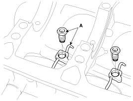
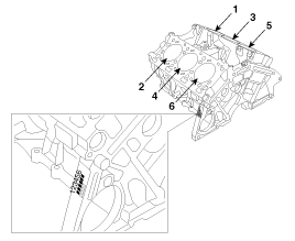
Install the oil jet(A).
Tightening torque :
29.4 ~ 34.3Nm (3.0 ~ 3.5kgf.m, 21.7 ~ 25.3lb-ft)
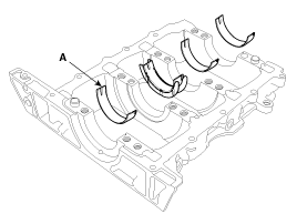
Install the crankshaft main bearings(A).
The upper bearings have the oil grooves of the oil holes ; The lower ones do not.
Aligning the bearing claw with the groove of the cylinder block, push in the four upper bearings(A).
Apply oil on the bearings at this moment.
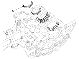
Place the crankshaft(A) on the cylinder block.
Aligning the bearing claw with the groove of the bedplate, push in the four lower bearings(A).
Apply oil on the bearings at this moment.
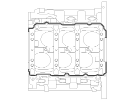
Place the bed plate on the cylinder block.
Standard liquid gasket : LOCTITE 5902
Check that the mating surfaces are clean and dry before applying liquid gasket.
Apply liquid gasket in a 3mm wide bead without stopping.
Assemble the bedplate in fifteen minutes after applying liquid gasket.
After assembly, wipe out flowed-off sealant to front face and rear crankshaft oil seal housing.
Install the bedplate bolts.
The bedplate bolts are tightened in several progressive steps.
If any of the bedplate bolts are broken or deformed, it must be replaced.
Tighten the No.18, 20, 21 bolts in its number order(18→20→21) with the specified torque.
Tightening torque :
29.4 ~ 33.3Nm (3.0 ~ 3.4kgf.m, 21.7 ~ 24.6lb-ft)
Tighten the No.1~16 bolts in two steps with the specified torque and angle below.
Do not reuse the No.1 ~ 16 bolts.
Tightening torque :
61.8 ~ 65.7Nm (6.3 ~ 6.7kgf.m, 45.6 ~ 48.5lb-ft) - 1st step
120° ~ 124° - 2nd step
Loosen the bolts No. 18, 20 and 21.
Tighten the No.17~25 bolts with the specified torque below.
Tightening torque :
29.4 ~ 33.3Nm (3.0 ~ 3.4kgf.m, 21.7 ~ 24.6lb-ft) - 1st step
Check that the crankshaft rotates smoothly.
Check the crankshaft end play, using a dial indicator.
End play
Standard : 0.1 ~ 0.3mm (0.0039 ~ 0.118in)
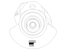
Using the SST(09231-H1210, 09231-H1100) and a plastic hammer, tap in a new oil seal(A) until SST surface is flush with the cylinder block.
At this time, the depth of the oil seal(A) from the cylinder block surface is 0.8mm(0.032in).
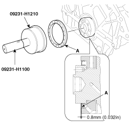
Before assembling oil seal, the hardened sealant or injurious material located on the boundary area between cylinder block and bed plate must be removed.
Apply engine oil to a new oil seal lip.
When pressing oil seal, confirm to direction and take care not to damage oil seal.
Install the driveplate(A).
Tightening torque :
117.7 ~ 127.5Nm (12.0 ~ 13.0kgf.m, 86.8 ~ 94.0lb-ft)
Install the piston rings.
No.1 and No.2 piston rings - assemble the rings with the 'Y' marks on the edge of the rings facing the cylinder head side. One end gap is placed at 180˚ opposite position with the other.
Oil ring - the end gap of the oil ring should be located with 180˚ to that of coil spring and 90˚ to that of No.1 ring.
Check that the oil ring assembly(oil ring and coil spring) can be turned smoothly toward any(clockwise or counterclockwise) direction.
Position the piston rings so that the ring ends are as shown below.
Assemble the piston and connecting rod.
Set the snap ring in one side of piston pin hole.
Apply sufficient engine oil or non-water-soluble press oil to outer surface of the piston, inner surface of piston pin hole and small end bore of the connecting rod before insering the piston pin.
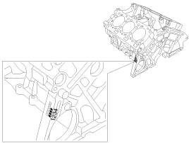
Insert the piston pin into the piston pin hose and the small end bore of connectong rod after setting the piston front marks(A) and the RH/LH marks(B) of the connecting rod facing to the timing chain.
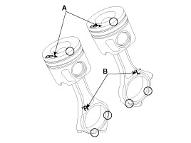
Marking the parts at the '○' points in the picture above makes the reassembly work much easier for its direction.
Set the snap ring in the other side after inserting the piston pin.
Install the connecting rod bearings.
Align the bearing claw with the groove of the connecting rod cap.
Install the piston and connecting rod assembly.
Before installing the piston, apply a coat of engine oil to the ring grooves and cylinder bores.
Remove the connecting rod caps, and slip short sections of rubber hose over the threaded ends of the connecting rod bolts.
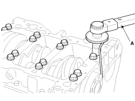
Install a ring compressor, check that the rings are securely in place, position the piston in the cylinder, and tap it in using the wooden handle(A) of a hammer.
Stop pushing after the rings go into the cylinder, and check the connecting rod-to-crank journal alignment before pushing the piston into place again.
Be careful for the oil jets not to be damaged by the connecting rods in this step.
Apply engine oil to the bolt threads. Install the rod caps with bearings, and tighten the bolts.
Tightening torque :
27.5 ~ 31.4Nm (2.8 ~ 3.2kgf.m, 20.3 ~ 23.1lb-ft) + 88°~ 92°
Maintain downward force on the ring compressor to prevent the rings from expending before entering the cylinder bore.
Installing order: No.1 and No.4 cylinders → No.3 and No.6 cylinders → No.2 and No.5 cylinders.
When installing the pistons in the order above and having a difficulty in pushing some pistons, rotating the crankshaft may make the installation easier.
