With the multi function switch in each position, make sure that continuity exists between the terminals below.
If continuity is not as specified, replace the multi-function switch
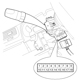
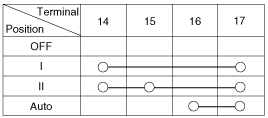
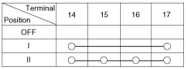
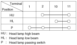
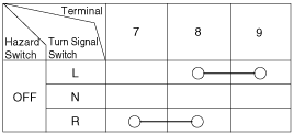

With the multi function switch in each position, make sure that continuity exists between the terminals below.
If continuity is not as specified, replace the multi-function switch


With the multi function switch in each position, make sure that continuity exists between the terminals below.
If continuity is not as specified, replace the multi-function switch.
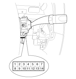
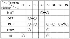

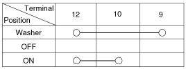
It will be able to diagnose defects of multifunction switch with scan tool quickly. Scan tool can operates actuator forcefully, input/output value monitoring and self diagnosis.
Select model and menu.
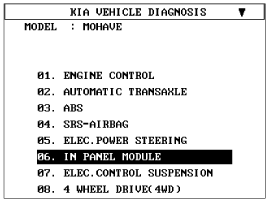
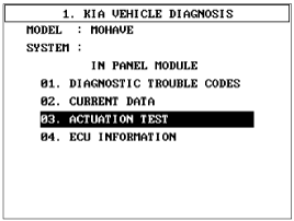
Select “In-panel module(IPM).
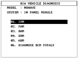
Select "Current data".
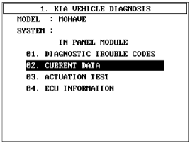
Check the input/output status of multifunction switch.
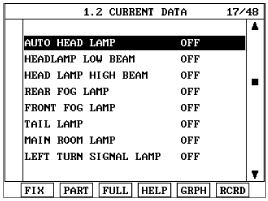
Select “Front Area Module(FAM)” or “Rear Area Module(RAM)”.
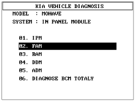
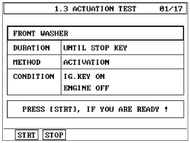
If you will check multifunction switch input data operation forcefully, select "Actuation test".
Disconnect the negative (-) battery terminal.
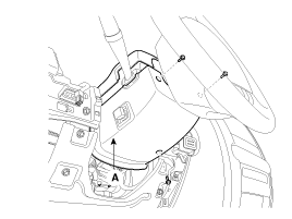
Remove the steering column upper and lower shrouds (A) after removing 3 screws.
(Refer to ST group - Steering column and shaft).
Remove the lighting switch (A) by pushing the lock pin (B) after disconnecting the connector.
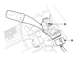
Remove the wiper switch (A) by pushing the lock pin (B) after disconnecting the connector.
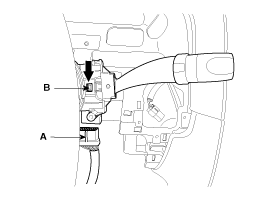
Install the wiper switch after connecting the connector.
Install the lighting switch after connecting the connector.
Install the steering column upper and lower shrouds.