
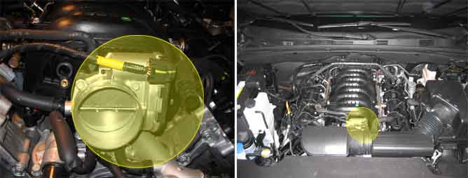
The Electronic Throttle Control(ETC) system is made of the components throttle body, Throttle Position Sensor(TPS)1&2 and Accelerator Position Sensor(APS) 1&2. TPS1&2 are sharing the same source voltage and ground.The throttle valve opening is control by throttle motor which is controlled by Engine Control Module(ECM).The opposite position indicator shows inverted signal characteristics.TPS1 output voltage increases smoothly in proportion with the throttle valve opening angle after starting. TPS2 output voltage decreases in inverse proportion with the throttle valve opening angle after starting. TPS provides feedback to the ECM to control the throttle motor in order to control the throttle valve opening angle properly in response to the driving condition.
If the deviation between the throttle position by TPS2 signal and the throttle position by ECM's model value is bigger than the threshold value under TPS1 error, ECM sets DTC P0221.
Item | Detecting Condition | Possible Cause |
DTC Strategy |
•
Plausibility check between |
•
Poor connection
•
TPS
•
ECM |
Enable Conditions |
•
Engine speed > 480rpm
•
ECT > 75C
•
Engine load < 95% | |
Threshold value |
•
I TPS1 Position – TPS2 Position I > 6.3% | |
Diagnosis Time |
•
0.5 sec | |
MIL On Condition |
•
1 driving cycle |
Fig. 1) Normal waveform of TPS1 & TPS2 with no accel padal depressed under IG ON condition