
Several control units are applied to electronically controlled vehicles. These units perform each control with informations from various sensors. Thus, sharing signal information from sensors is needed, so CAN communication type whose communication speed is high and insensitive to electrical noise by spark generation is adopted to controlling power-train(engine, atutomatic transaxle, ABS, TCS, ECS)
A/T, ESP, ABS control units share the informations that Engine rpm, APS signal, gear position, Torque reduction signal, using CAN communication to confirm active controlling.
TCM set this code If Pressure control valve is out of control due to too much increase of Engine rpm.(MIN "ON")
Item | Detecting Condition | Possible Cause |
DTC Strategy |
•
Check signal |
•
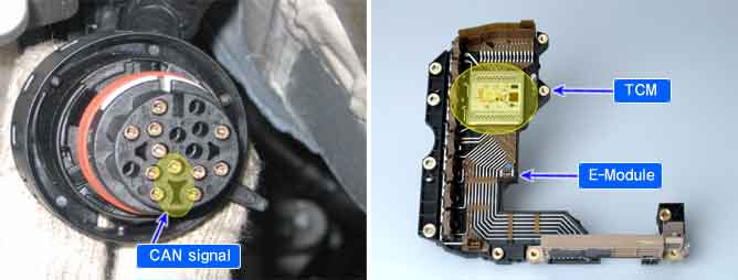
Crank angle sensor(CKP) |
Enable Conditions |
•
Lever position = Not P,R, N range
•
Engine rpm = normal
•
Out of P,R,N range and after shifting 0.3 second | |
Threshold Value |
•
Engine rpm > 5000 RPM | |
Diagnostic Time |
•
Immediately | |
Fail Safe |
•
High speed : fixed at 5th gear, low speed : fixed at 3rd gear
•
Reverse : Shift lock(Push "Unlock button → possible to shift) (priority :3) |
The function with the higher priority will aiways take precedence. However, a low-priority is not overruled by a higher priority function.
Functions from different priority categories can also run in parallel. It is important to note which function will take precedence in this case.
In such an event it is possible for a substitute function with low priority not be carried out if a second, higher-priority function is present. This has been taken into account when compiling the priority list and is international.
The mechanical emergency run function must always have the highest priority, since from the electrical standpoint it is the only safe condition.
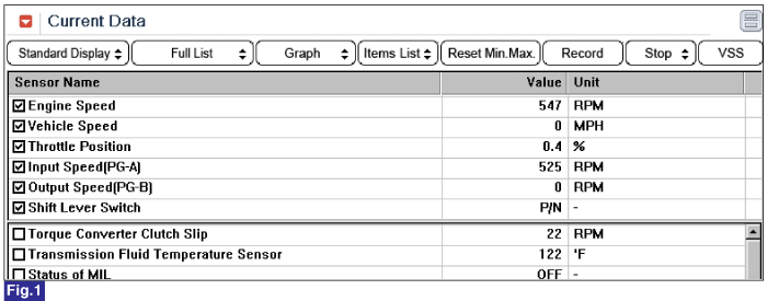
Fig 1) Engine rpm When Idle