Ignition "ON" & Engine "OFF".
Disconnect "ATM Control Unit(CLG01-C)" connector.
Connect scantool and select 'Simulation Function"on the scanner.
Simulate duty pulse on signal terminal of "Input Speed Sensor 1 & 2" with scanner.
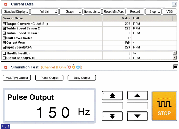
Fig 1) Turbin Speed Sensor 2 : 150Hz → 227rpm
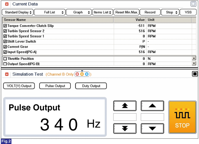
Fig 2) Turbin Speed Sensor 2 : 340Hz → 5160rpm
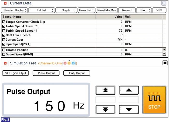
Fig 3) Turbin Speed Sensor 1 : 150Hz → 79rpm
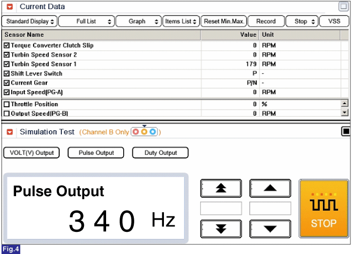
Fig 4) Turbin Speed Sensor 1 : 340Hz → 179rpm
※ The values are subject to change according to vehicle model or conditions
Is "Input Speed Sensor 1 & 2" signal value changed according to simulation frequency?
![]() | ▶ Thoroughly check connectors for looseness, poor connection, bending, corrosion, contamination, deterioration, or damage. Repair or replace as necessary and then go to "Verification of Vehicle Repair" procedure. |
![]() | ▶ Substitute with a known-good TCM/PCM and check for proper operation. If the problem is corrected, replace TCM/PCM as necessary and go to "Verification of Vehicle Repair" procedure. |