
The ratio monitoring controls the nominal gear box ratio to the real gear box ratio. While driving in a gear(reverse, first second, third…) there is a calibrated rationality check between turbine speed and output speed of the corresponding gear.
While up or down shifting from one gear to another there is a calibrated rationality check between turbine speed and output speed of the corresponding shift. While engaging the gear there is a calibrated rationality check between turbine speed and output speed of the corresponding shift if the actual output speed is higher or equal than a calibrated threshold.
While engaging the gear when the actual output speed is lower than the threshold there is a rationality check on the turbine speed.
TCM set this code if the value of input speed(turbine speed) is not equal to the value of the output speed, when multiplied by the 2nd gear ratio, while the transaxle is engaged in 2nd gear. If this code outputted, Check the Engine system first and then follow this procedure.(MIL ON : 2 driving Cycle)
Item | Detecting Condition | Possible Cause | |
DTC Strategy |
•
Gear ratio monitoring |
•
Check the Engine system and DTC
•
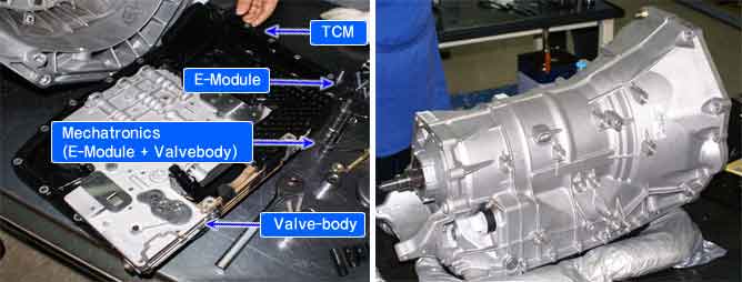
Mechatronics(E-module + Valvebody) => Solenoid valve"1"&3"
•
Replace ATM | |
Enable Conditions |
•
2nd gear shifting
•
Shifting monitoring status | ||
CASE1 |
•
Output speed ≤ 50 rmp | ||
CASE2 |
•
2nd gear shifting with 0.5 second
•
Output speed ≤ 50 rmp | ||
Threshold Value | CASE1 |
•
Actual engaging gear ratio ≥ target gear ratio
•
Actual engaging gear ratio < target gear ratio | |
CASE2 |
•
Input speed when start to monitoring - actual Input speed < 40 rpm or
•
Input speed when start to monitoring - actual Input speed ≥ 40 rpm | ||
Diagnostic Time |
•
3times function check | ||
Fail Safe |
•
No learning control
•
Fixed at 5th gear (priority : 3) | ||
The function with the higher priority will aiways take precedence. However, a low-priority is not overruled by a higher priority function.
Functions from different priority categories can also run in parallel. It is important to note which function will take precedence in this case.
In such an event it is possible for a substitute function with low priority not be carried out if a second, higher-priority function is present. This has been taken into account when compiling the priority list and is international.
The mechanical emergency run function must always have the highest priority, since from the electrical standpoint it is the only safe condition.
gear position | ON SOL. | SOL.1 | SOL.2 | SOL.3 | SOL. 4 | SOL. 5 | SOL. 6 |
P | OFF | 48mA | 848mA | 48mA | 48mA | -O- | OFF |
R | OFF | 48mA | 48mA | 48mA | 48mA | -O- | OFF |
N | OFF | 48mA | 848mA | 48mA | 48mA | -O- | OFF |
D1 | OFF | 848mA | 848mA | 48mA | 48mA | -O- | -O- |
D2 | OFF | 848mA | 848mA | 848mA | 848mA | -O- | -O- |
D3 | OFF | 848mA | 48mA | 48mA | 848mA | -O- | -O- |
D4 | ON | 848mA | 848mA | 48mA | 48mA | -O- | -O- |
D5 | ON | 48mA | 48mA | 48mA | 48mA | -O- | -O- |
D6 | ON | 48mA | 848mA | 848mA | 48mA | -O- | -O- |
-O- : variable control
Fig 1) Solenoid valves in 2nd gear
Fig 2) Solenoid valves in 2nd gear-graph
Fig 3) Solenoid operating status - down shift 3rd to 2nd gear