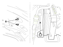
Loosen the ABS HECU bracket bolt (A) and nuts (B), then remove HECU and bracket.
Tightening torque:
16.7 ~ 25.5 N.m (1.7 ~ 2.6 kgf.m, 12.3 ~ 18.8 lb-ft)
Turn the ignition switch OFF and disconnect the negative (-) battery cable.
Remove the air cleaner assembly. (Refer to the Engine Mechanical System group - Intake Manifold)
Remove the ECM. (Refer to Fuel system group - Engine Control Module)
Remove the front wheel guard.
Loosen the ABS HECU bracket bolt (A) and nuts (B), then remove HECU and bracket.
Tightening torque:
16.7 ~ 25.5 N.m (1.7 ~ 2.6 kgf.m, 12.3 ~ 18.8 lb-ft)

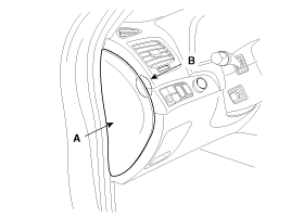
Remove the crash pad side cover (A) by using a hole (B).
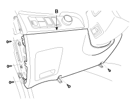
Remove the lower panel (A) after loosening the mounting screws.
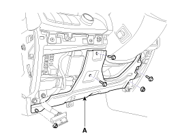
Remove the reinforcing panel (A) after loosening the mounting bolts and nuts.
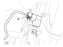
Disconnect the stop lamp switch connector (A).
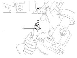
Remove the snap pin (A) and joint pin (B).
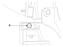
Remove the mounting bracket bolts (B).
Tightening torque:
16.7 ~ 25.5 N.m (1.7 ~ 2.6 kgf.m, 12.3 ~ 18.8 lb-ft)
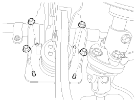
Remove the brake pedal member assembly mounting nuts.
Tightening torque:
12.7 ~ 15.7 N.m (1.3 ~ 1.6 kgf.m, 9.4 ~ 11.6 lb-ft)
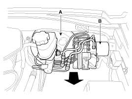
In order to separate the brake booster assembly (A) and the HECU assembly (B) from the dash panel, pull then in the direction of the arrow.
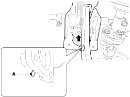
Pull out the hook (A) from the dash panel in the direction of the arrow, and then remove the brake pedal assembly.
Turn the ignition switch OFF and disconnect the negative (-) battery cable.
Remove the air cleaner assembly. (Refer to the Engine Mechanical System group - Intake Manifold)
Remove the ECM. (Refer to Fuel system group - Engine Control Module (ECM)
Remove the front wheel guard.
Loosen the ABS HECU bracket bolt (A) and nuts (B), and then remove HECU and bracket.
Tightening torque:
16.7 ~ 25.5N.m (1.7 ~ 2.6kgf.m, 12.3 ~ 18.8lb-ft)

Remove the crash pad side cover (A) by using a hole (B).

Remove the lower panel (A) after loosening the mounting screws.

Remove the reinforcing panel (A) after loosening the mounting bolts and nuts.

Disconnect the adjust cable (A).
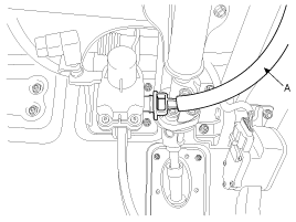
Disconnect the stop lamp switch connector (A).
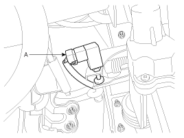
Remove the snap pin (A) and clevis pin (B).
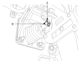
Remove the mounting bracket bolts (B).
Tightening torque:
16.7 ~ 25.5 N.m (1.7 ~ 2.6 kgf.m, 12.3 ~ 18.8 lb-ft)
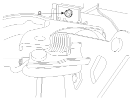
Remove the brake pedal member assembly mounting nuts.
Tightening torque:
12.7 ~15.7 N.m (1.3 ~1.6 kgf.m, 9.4 ~11.6 lb-ft)
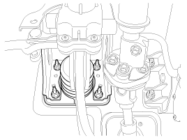
In order to separate the brake booster assembly (A) and the HECU assembly (B) from the dash panel, pull then in the direction of the arrow.

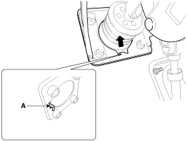
Pull out the hook (A) from the dash panel in the direction of the arrow, and then remove the brake pedal assembly.
Check the bushing for wear.
Check the brake pedal for bending or twisting.
Check the brake pedal return spring for damage.
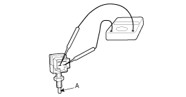
Check the stop lamp switch.
Connect a circuit tester to the connector of stop lamp switch, and check whether or not there is continuity when the plunger of the stop lamp switch is pushed in and when it is released.
The stop lamp switch is in good condition if there is no continuity when plunger(A) is pushed.
Installation is the reverse of removal.
Before installing the pin, apply the grease to the clevis pin.
Use a new snap pin whenever installing.
Check the brake pedal operation.