Description
system outline

An optimal seat position set by a driver can be memorized in Power seat unit by IMS SW, which enables restoration of seat position set by the driver despite

Playing of this function during drive is banned for safety reasons, and it has emergency stop function of restoration and gearing operation as well

Input Specification
1.

IGN2

IGN is judged by local SW “IGN2”and CAN data “Ignition sw Sts”

2.

Seat manual SW: Seat Input

(1)

Slide FR / RR manual SW

SW that moves slide motor of a seat forward or backward

(2)

Recline FR / RR SW

SW that moves recline motor of a seat forward or backward

(3)

FR height up / down manual SW

SW that moves front height motor of a seat upward or downward

(4)

RR height up / down manual SW

SW that moves rear height motor of a seat upward or downward

3.

Seat position sensor (pulse signal)

A.

A sensor to sense the movement of slide, recline, FR height and RR height motor.

4.

“P” position SW

This SW detects parking state of transmission.

Get-on/off gearing and memory storage are not allowed in positions other than “P”. (AT only)

(“P” position SW is used because INH “P” detection is not possible when IGN is off)

“P” Position SW is used in case that CAN is time out

5.

IMS SW: It Is transmitted to IMS with CAN communication after DDM input

(1)

SET SW

SW that sets the position of seat by a driver at memory allowed state

(2)

MEM 1, MEM 2 SW

SW that memorizes and plays the position of seat set by a driver

6.

CAN communication line (CAN Hi, CAN Low)

IMS communicates IPM, FAM, DDM, ADM, RAM, CLU, SCM, SMK and PDM through CAN BUS

(At the speed of 50kbps)

7.

Limit SW

SW that prevents restriction of seat and its contact point is normal close type.

Functional specification
1.

Output time

Buzzer output: 0.1 sec. On, 0.4 sec. off

2.

Output condition

*When it is allowed Memory mode (memory SW on): once

*When Memory storage mode is completed (Position SW on): twice

*When Memory mode is played (Position SW on): once

*When Easy Access operation is set (IMS Auto Sw ON): twice

*When Easy Access operation is canceled (IMS Auto Sw OFF) : once

*When error occurs due to sensor failure: 10 times

The conduct of input signal chattering

3.

40ms objects : input SW

* Slide, recline, FR height, RR height manual SW

* ”P” position SW

* Slide FR/RR limit SW

* Recline FR/RR limit SW

4.

IGN is judged by local SW “IGN2” and CAN data “Ignition Sw Sts”

Function
Manual operation
1.

Manual operation of seat

Seat manual SW manipulation enables seat operation by the input of manual SW.

Manual operation is always possible for slide, recline, front height and rear height even though ECU B+ is off as long as IGN2 is on.

Memory storage operation
1.

Memory permission operation

If CAN BUS data “IMS Memory Commend” transmitted from DDM according to Memory SW is SET, it enters Memory permission mode, and if IMS receives “IMS Memory Commend SET”, IMS outputs buzzer once.

2.

Memory operation

If CAN BUS data “IMS Memory Commend” transmitted from DDM according to handling position SW is MEMORY1 or MEMORY2, IMS outputs buzzer twice and memorize the current seat positions

(DDM transmits Memory order only when position SW input happens within 5 sec from Memory SW off->on, and passage of 5 sec in Memory permission mode will cancel the mode.)

3.

Memory conditions

Failure to meet any one of the following conditions will trigger ban or cancellation of Memory permission. (DDM determines if the following conditions are met or not, and only if all four conditions are met, it transmits Memory permission order (“IMS Memory Commend”: “SET “) and Memory order (“IMS Memory Commend”:“Memory1” or “Memory2”).

① CAN BUS data “Ignition sw Sts” transmitted from IPM is “RUN”.

② CAN BUS data “Inhibitor Sw Sts” transmitted from CLU is “P”.

③ CAN BUS data “Vehicle Speed” transmitted from CLU is “3km/h” or below.

④ Below 5 sec. After Memory SW on-> off.

4.

Memory set does not have a limit in terms of the number of inputs

(Storage by Memory SW manipulation once is limited to once)

5.

If Memory order is received during Get-on gearing or play operation, halt auto control and remember the current position while remembering the position where Memory order is received if it is received during operation by manual SW for seat.

Memory play operation
1.

Play operation

If CAN BUS data (IMS Memory Commend) transmitted from DDM by position SW manipulation is “RETURN 1” or “RETURN 2”, Output a buzzer once and automatically put seat back to a remembered position,

2.

Halt conditions

DDM will transmit CAN BUS data to generate Memory play order only in case that two conditions of ①② (in the following 5) items are met and one condition of ③, ④ items is met.

① CAN BUS data “Inhibitor Sw Sts” transmitted from CLU is “P”.

② CAN BUS data “Vehicle Speed” transmitted from CLU is “3km/h” or below

③ In case that the MEM1/MEM2 SW of IMS SW is ON, if driver door open or in 30 seconds after driver door close

④ CAN BUS data “Ignition Sw Sts” transmitted from IPM is “RUN

⑤ No manual SW manipulation for seat (determined by IMS)

3.

Halt conditions (determined by IMS)

Failure to meet any one of the following during play operation will halt the operation

① CAN BUS data “Inhibitor Sw Sts” transmitted from CLU is “P”.

② CAN BUS data “Vehicle Speed” transmitted from CLU is “3km/h” or below

③ The limit sw of moving direction. is ON during operation

④ In case that target position of motor (±6 EDGE) is not arrived

⑤ No manual SW manipulation for seat

However, buzzer output will still take place in order to inform the user of play operation of other units when play order is received even though manual SW for seat is on.

4.

Others

① Play operation not recorded in the MEM1/2 will not be conducted and there will be no buzzer output

② If other data is received during Play operation, the most recent play signal will take precedence

③ If engine is started(if “Ignition Sw Sts” is “START”) during Play operation, halt Play operation, and resume it toward target position 100ms after “Ignition Sw Sts” is returned to “RUN”.

However, if the START state lasts over 5 sec., it will not resume even after returning to RUN

④ If Play order is received during engine start(if “Ignition Sw Sts” is “START”), Play operation is inhibited.

⑤ If input from manual SW during Play operation occurs. halt all Play operations of seat.

⑥ If an error occurs during manual operation of seat, do not delete Memory.

5.

Operation control

① Prioritization of operations

Motor starting is delayed for 100ms respectively in case of auto control to prevent rush current from overlap when motors are running, and it follows the following order.

SLIDE > RECLINE > FR HEIGHT > RR HEIGHT

② Memory play is conducted in the following order, and delay time for each motor is as follows.
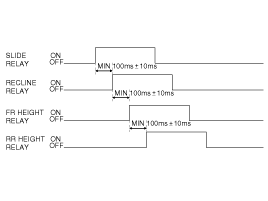
Continuous cooperation TIMER value for each motor (Except operations by manual SW)

Slide: 20 sec., recline: 35 sec., front height: 10 sec., rear height: 15 sec

③ Control when turning to the opposite direction

When motor has to be run in a reverse direction during Easy access function gearing or play operation, stop the operation immediately, wait for 100ms and then try operation to the reverse direction.

④ If the difference between memorized position and the current one is below specified value, motor will not run even though play data is received.

* Slide, recline, front height, rear height: 12 EDGE (6PULSE)

* Slide, recline, FR height, RR height: 12EDGE (6PULSE)

⑤ Operation will stop upon reaching Motor’s target point when conducting Easy access function gearing or play operation.
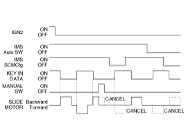
Easy access function gearing operation
1.

Easy access function gearing operation is allowed only when CAN DATA (IMS Auto Sw) transmitted from DDM is ON

2.

If “SET SWITCH” pushes over 10 sec, it will enable Easy access function gearing operation to set or cancel

( when Get-on gearing operation is set, output buzzer twice, / when Get-off gearing operation cancel, output buzzer once ),

3.

Get-off gearing operation is set in case that CAN DATA (IMS SCM Cfg) transmitted from IPM is “1”

( 0: Not Equipped, 1: Equipped ALL ON, 2: Equipped SCM ON, 3: Equipped ALL OFF )

4.

If a key is removed and CAN BUS data “Key Reminder Sw Sts” transmitted from IPM changes from “on” to “off”, the seat slide will move 50mm backward based on the key out point.

If slide rear limit becomes off in the middle of backward operation, get-off gearing will not be conducted.

5.

If the key is inserted and CAN BUS data “Key Reminder Sw Sts” transmitted from IPM change from “on” to “off”, slide motor will move to the position of key out

6.

Conditions to ban or halt Easy access function gearing operation

The following conditions will be identified and processed by IMS, and if any one of the following conditions is met, Easy access function gearing operation will be prevented or halted

① When “P” position SW is not on.

② When “Vehicle Speed” in CAN BUS data transmitted from CLU is “3km/h” or faster

③ When seat is under manual SW operation

④ When play operation is received during get-on gearing operation

⑤ When CAN data (IMS Auto Sw) transmitted from DDM is off

(Operation is completed in case that CAN data (IMS Auto Sw) changes form “ON” to “OFF” during operation)

7.

When control is halted in the middle of backward operation, the remaining operation will not be completed, and when returning, it will return just as much as it retreated

8.

It will move to key out point in case of Get-on gearing by key in despite manual SW input during or after backward operation

9.

Renewal condition of get-on gearing operation

① When CAN data (Ignition Sw Sts) changes from “RUN” to OFF and when CAN data (Key Reminder Sw Sts) changes from “ON" to “OFF”, Unit Remember position of “IGN = OFF“ and “KEY OUT “

② When manual SW is operated during KEY IN

③ When play operation is accomplishing

④ When pulse difference between previously memorized position and current position is beyond 6 pulse.

Setting limit
1.

SLIDE, RECLINE

Limit SW is installed on both front/rear of the slide and the recline, and motor is not allowed to run under Limit SW off during manual SW operation, memory playing/Easy access function gearing operation.

2.

RR HEIGHT, FR HEIGHT

Since there is no Limit SW, set an arbitrary limit position as the following

① Immediately stop control and set its position to the limit position of its proceeding direction if input of over 6 pulses in 2 sec. is not fed during memory playing after attaching battery (Setting Limit on the opposite is the same).

② Once a certain limit is set, memory playing that goes beyond set range is not allowed to run to prevent motor damage by mechanical lock

③ Renew limit position if pulses are fed normally beyond its limit position Already set by manual operation

Detecting error or handling error
1.

Detecting error for seat

Unit judges motor to be error if the following conditions occur during manual SW operation,Easy access function gearing operation or memory playing.

① Error when pulse is not fed

Item

Slide

Recline

Fr height

Rr height

Error condition

Below 6 pulses in 2 sec.

Below 6 pulses in 1 sec

Prerequisite

FR/RR Limit SW On

Limit setting complete

* Stop the related motor if an error is detected during playing or Easy access function gearing operation.

* Stop the corresponding motor if an error is detected during manual operation (Excluding slide motor).

② If seat sensor Vcc below 1V is detected by 40ms,

=> Return if seat sensor Vcc is 4V or more.

* Stop all seat motors running if seat sensor Vcc error is detected during playing or Easy access function gearing operation. (No buzzer output)

2.

Handling error

If errors in the above are discovered, regard them as harness disconnection or sensor failure, and conduct the following measures.

A.

Stop auto control (play or Easy access function gearing operation) if it is under auto control and set off buzzer 10 times (however, have motors other than the one with an error operate normally).

B.

Set off alarm again in case of recurrence of error after restoration of a motor with an error.

C.

Complete alarm 10 times though it comes back to normal during error alarm.

D.

Stop alarm if receiving memory recall or play order, and set off buzzer in the corresponding function.

E.

Manual operation control is allowed even for a motor with errors.

F.

Set off buzzer if memory or play order is received even during error.

G.

The timing to lift auto control suspension is when repair for the failing motor is completed, and the criteria for the completion point are as follows:

Seat: if signal input is normal with over 6 pulses within a sec. from position sensor of a motor with an error caused by manual SW

Input/Output Specification
Connector Pin Lay Out
IMS input/output pin information

No

Signal Name

I/O

Contents

Remark

A1

-

-

-

A2

FR Height Motor Up

O

FR Height Motor Up Output

A3

RR Height Motor Up

O

RR Height Motor Up Output

A4

Recline Motor FR

O

Recline Motor FR Output

A5

Slide Motor FR

O

Slide Motor FR Output

A6

-

-

-

A7

FR Height Motor Down

O

FR Height Motor Down Output

A8

-

-

-

A9

-

-

-

A10

RR Height Motor Down

O

RR Height Motor Down Output

A11

Recline Motor RR

O

Recline Motor RR Output

A12

Slide Motor RR

O

Slide Motor RR Output

B1

GND(Power)

I

Power B+ For Operating Motor

B2

-

-

-

B3

B+(Power)

I

Power B+ For Operating Motor

B4

GND(Power)

I

Power GND for Operating Motor

B5

B+(Power)

I

Power GND for Operating Motor

C1

Slide FR Limit SW

I

Slide FR Limit SW Input

Normal Close

C2

Recline FR Limit SW

I

Recline FR Limit SW Input

Normal Close

C3

-

-

-

C4

Slide FR Manual SW

I

Slide FR Manual SW Input

On : GND

C5

Recline Fr Manual SW

I

Recline FR Manual SW Input

On : GND

C6

FR Height Up Manual SW

I

FR Height Up Manual SW Input

On : GND

C7

RR Heigth Up Manual SW

I

RR Height Up Manual SW Input

On : GND

C8

Slide Motor Sensor

I

Slide Motor Sensor Input

Pulse Signal

C9

RR Height Motor Sensor

I

RR Height Motor Sensor Input

Pulse Signal

C10

Sensor Vcc(Seat)

O

VCC For Operating Sensor

C11

Slide RR Limit SW

I

Slide RR Limit SW Input

Normal Close

C12

Recline RR Limit SW

I

Recline RR LIMIT SW Input

Normal Close

C13

-

-

-

C14

Slide RR Manual SW

I

Slide RR Manual SW Input

ON : GND

C15

Recline RR Manual SW

I

Recline RR Manual SW Input

ON : GND

C16

FR Height Down Manual SW

-

FR Height Down Manual Sw Input

ON : GND

C17

RR Height Down Manual SW

-

RR Height Down Manual Sw Input

ON : GND

C18

Recline Motor Sensor

I

Recline Motor Sensor Input

PULSE SIGNAL

C19

FR Height Motor Sensor

I

FR Height Motor Sensor Input

PULSE SIGNAL

C20

Sensor GND(Seat)

O

GND For Operating Sensor

D1

-

-

-

D2

-

-

-

D3

-

-

-

D4

CAN (Hi)

I/O

CAN Bus Line

D5

CAN (Low)

I/O

CAN Bus Line

D6

-

-

-

D7

IGN2

I

IGN2 Input

BAT

D8

B+(ECU)

I

ECU Power Input

BAT

D9

-

-

-

D10

“P” Position SW

I

“P” Position SW Input

On : GND

D11

-

-

D12

-

-

D13

-

-

D14

GND(ECU)

I

ECU GND

D15

-

-

D16

-

-

Яндекс.Метрика