4.
Remove the glow plug wiring and glow plugs. (Refer to EE group)
Remove the timing chain. (Refer to Timing system in this group)
Remove the intake manifold and exhaust manifold. (Refer to Intake and exhaust system in this group)
Remove the injectors, high pressure pipe and delivery pipe. (Refer to FL group)
Remove the glow plug wiring and glow plugs. (Refer to EE group)
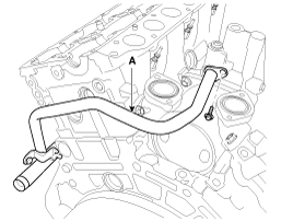
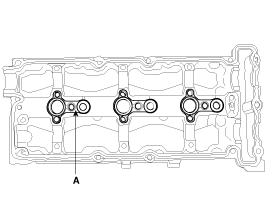
Disconnect the vacuum hose, and then remove the water outlet pipe (A).
Remove the EGR pipe & hose assembly (A).
Remove the water outlet duct (A).
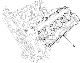
Remove the LH/RH cylinder head cover (A).
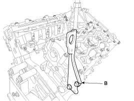
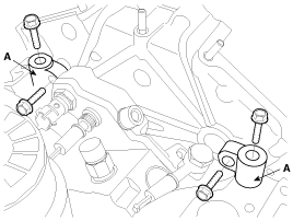
Remove the front and rear enging hanger (A, B).
Remove the LH/RH camshaft bearing ladder.
Remove the LH upper head seal (A).
Remove the LH camshaft bearing ladder (B).
Remove the RH upper head seal (A).
Remove the timing chain case bracket (B).
Remove the RH camshaft bearing ladder (C).
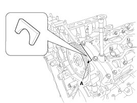
Remove the sealing caps (A).
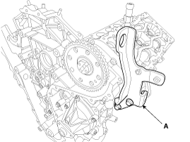
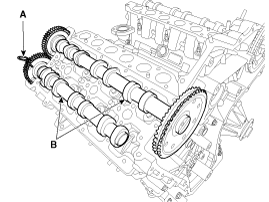
Insert the stopper pin (A) into the LH/RH exhaust camshaft scissors gear, and then remove the camshafts (B).
If the exhaust camshaft is removed when the stopper pin is not installed on the scissors gear of the exhaust camshaft, the main gear and scissors gear are distorted. In this csae, assemble a pin on the exhaust camshaft with the main gear and scissors gear aligned and then install the camshaft.
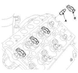
Remove the cam follower assembly (B) and HLA (Hydraulic Lash Adjuster) (A).
After removing it, HLA shall be held upright so that oil in it should not spill and be assured that dust does not adhere to it.
Remove the water hose and pipe assembly (A).
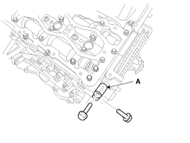
Remove the timing chain case bracket (A).
Remove the cylinder head bolts reverse order of installation. (Refer to installing order)
Do not reuse the cylinder head bolts.
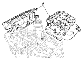
Remove the cylinder head (A) quietly in order not to damage the gasket with the bottom part of the end.
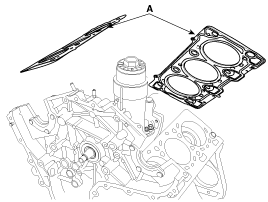
Remove the cylinder head gasket (A).
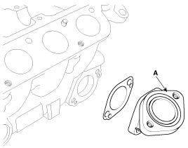
Remove the water outlet fitting (A).
Using the SST(09222-2A100, 09222-3K000), compress the spring and remove the retainer locks.
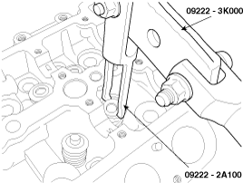
Remove the valve, valve spring and spring retainer.
Thoroughly clean all parts to be assembled.
Before installing the parts, apply fresh engine oil to all sliding and rotating surface.
Replace oil seals with new ones.
Install the valves.
Using the SST (09222-2A000)(A), push in a new stem oil seal.
Do not reuse old valve stem oil seals.
Incorrect installation of the seal could result in oil leakage through the valve guides.
Apply engine oil on a valve stem seal surface contacting with a valve guide or a valve guide outer surface before installing a valve stem seal.
Install the valve, valve spring and spring retainer.
Apply engine oil on the valves when installing.
Using the SST(09222-2A100, 09222-3K000), compress the spring and install the retainer locks. After installing the valves, ensure that the retainer locks are correctly in place before releasing the valve spring compressor.
Lightly tap the end of each valve stem two or three times with the wooden handle of a hammer to ensure proper seating of the valve and retainer lock.
Install the water outlet fitting (A).
Tightening torque :
9.8 ~ 11.8N.m (1.0 ~ 1.2kgf.m, 7.2 ~ 8.7lb-ft)
Clean the cylinder head and the cylinder block surfaces contacting with their gaskets.
Inspect for cylinder head flatness. Using a precision straight edge and feeler gauge, measure the surface the contacting the cylinder block and the manifolds for warpage.
Flatness of cylinder head gasket surface :
Less than 0.05mm (0.0020in)
Less than 0.03mm(0.0012in.) - 100mm×100mm
Less than 0.01mm(0.0004in.) - 20mm×20mm
Flatness of manifold mating surface :
Less than 0.016mm(0.0006in.)
Less than 0.013mm(0.0005in.) - 25mm×25mm
Select the cylinder head gasket.
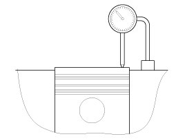
Measure the piston protrusion from the upper cylinder block face on the twelve places (A ~ F for each bank) at TDC (top dead center).
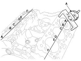
Select the gasket in the table below using the average value of the six piston protrusions. If an average value of a piston is over than the each rank limit, use one rank thicker gasket than the specified one in the table below.
Grade(A) | A | B | C | |
Average of piston protrusion | 0.310 ~ 0.410mm | 0.410 ~ 0.510mm | 0.510 ~ 0.610mm | |
Limit of each rank extant | 0.460mm | 0.560mm | - | |
Gasket thickness(compressed) | 1.1 ± 0.04mm | 1.2 ± 0.04mm | 1.3 ± 0.04mm | |
Part No. | Left bank | 22311 - 3A010 | 22311 - 3A000 | 22311 - 3A020 |
Right bank | 22312 - 3A010 | 22312 - 3A000 | 22312 - 3A020 | |
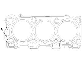
Install the LH gasket so that the identification mark (A) faces toward the timing chain side.
Install the RH gasket so that the identification mark (A) faces toward the transaxle side.
Install the cylinder head gasket (A) on the cylinder block.
Be careful of the installation direction.
Place the cylinder head quietly in order not to damage the gasket with the bottom part of the end.
Put on a lid on the intake port or the water outlet fitting in order for some materials such as bolts not to get inside.
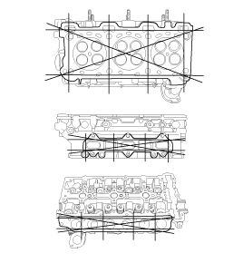
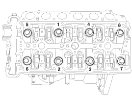
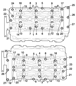
Tighten the eight cylinder head bolts on each bank, in several passes, in the sequence shown.
Tightening torque
1st step : 56.9 ~ 60.8 N.m (5.8 ~ 6.2 kgf.m, 41.9 ~ 44.8 lbf-ft)
2nd step : 88 ~ 92˚
3rd step : 118 ~ 122˚
Do not reuse the cylinder head bolts.
Install the timing chain case bracket (A). Tighten the vertical-direction bolts slightly first and then the horizontal-direction ones and the vertical-direction ones with the specified torque below.
Tightening torque :
19.6 ~ 25.5N.m (2.0 ~ 2.6kgf.m, 14.5 ~ 18.8lb-ft)
Install the water pipe and hose assembly (A).
Tightening torque :
9.8 ~ 11.8N.m (1.0 ~ 1.2kgf.m, 7.2 ~ 8.7lb-ft)
Install the camshafts and measure the end play.
Camshaft end play
Standard : 0.05 ~ 0.15mm (0.0020 ~ 0.0059in)
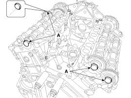
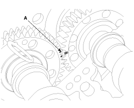
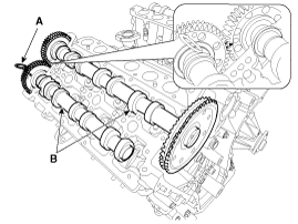
Align the marks (A) on the sprockets.
After measuring the end play, remove the camshafts.
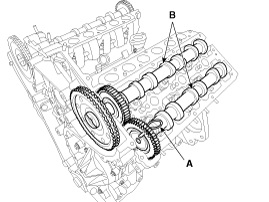
After applying oil, install the HLA (hydraulic lash adjuster) (A) and the cam follower assembly (B).
Until installing, HLA shall be held upright so that oil in it should not spill and be assured that dust does not adhere to it.
HLA should be inserted carefully to the cylinder head not to spill engine oil.
If engine oil has spilled out of the lash adjuster, HLA bleeding should be performed according to the below procedure.
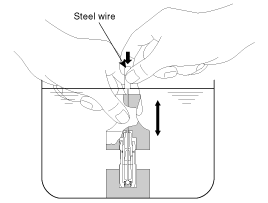
HLA bleeding procedure
Stroke the lash adjuster in engine oil by pushing its cap 4 to 5 times while pushing the ball down slightly using a hard steel wire. Be careful not to give the ball a hard push because the ball weighs just several grams.
If installing with engine oil spilling out of the lash adjuster and air in it, it might make an abnormal noise.
Wipe out oil on the upper surface of the cylinder head.
Install the LH/RH camshafts (B) with stopper pin (A) is assembled on the exhaust camshaft with the main gear and scissors gear aligned.
Align the marks on the sprockets.
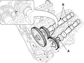
Pressing the exhaust camshafts, take out the stopper pin from their sprockets.
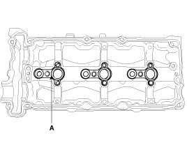
Install the LH/RH injector packings (A) on the camshaft bearing ladder.
Install the sealing caps (A) with applying sealant around the cap.
Sealant : LOCTITE 5902
Bead Width : ¢2.2 ± 0.4 mm
Reassemble the camshaft bearing ladder within 15 minutes after applying.
Install the camshaft bearing ladder.
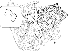
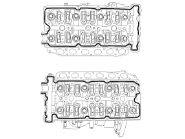
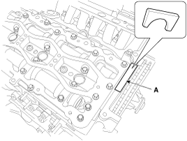
Apply sealant to the surface of LH/RH cylinder head as following illustration.
Sealant : LOCTITE 5902
Bead Width : ¢2.2 ± 0.4 mm
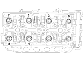
Tighten the bolts with the sequence and the torque below.
Tightening torque :
13.7 ~ 15.7N.m (1.4 ~ 1.6kgf.m, 10.1 ~ 11.6lb-ft)
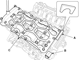
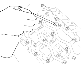
Apply sealant to the upper head seal as following illustration.
Sealant : LOCTITE 5900H, TH1217H
Bead Width : ¢2.5mm
Install the LH/RH upper head seal (A).
Reassemble the upper head seal within 5 minutes after applying.
Install the timing chain case bracket (A). Tighten the vertical-direction bolt slightly first and then the horizontal-direction ones and the vertical-direction one with the specified torque below.
Tightening torque :
19.6 ~ 25.5N.m (2.0 ~ 2.6kgf.m, 14.5 ~ 18.8lb-ft)
Apply oil on the camshafts sufficiently.
Install the front and rear enging hanger (A, B).
Tightening torque :
19.6 ~ 26.5N.m (2.0 ~ 2.7kgf.m, 14.5 ~ 19.5lb-ft)
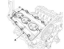
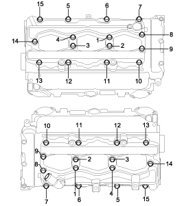
Install the cylinder head cover (A) with the sequence and the torque below.
Tightening torque :
9.8 ~ 11.8N.m (1.0 ~ 1.2kgf.m, 7.2 ~ 8.7lb-ft)
Install the water outlet duct (A).
Tightening torque :
9.8 ~ 11.8N.m (1.0 ~ 1.2kgf.m, 7.2 ~ 8.7lb-ft)
Install the EGR pipe & hose assembly (A).
Tightening torque :
9.8 ~ 11.8N.m (1.0 ~ 1.2kgf.m, 7.2 ~ 8.7lb-ft)
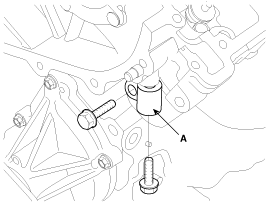
Install the water outlet pipe (A), and then connect the vacuum hose.
Tightening torque :
9.8 ~ 11.8N.m (1.0 ~ 1.2kgf.m, 7.2 ~ 8.7lb-ft)
Install the glow plugs and wiring. (Refer to EE group)
Install the injectors, high pressure pipe and delivery pipe. (Refer to FL group)
Install the intake manifold and exhaust manifold. (Refer to Intake and exhaust system in this group)
Install the timing chain. (Refer to Timing system in this group)
