
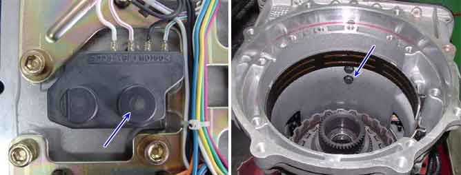
The Input Sensor of RXC Auto transmission is composed of S1(Sensor1) and S2(Sensor2). S1 inputs signal to TCM only at 4th gear and S2 does at 1st, 2nd, 3rd, 4th and 5th gear. Therefore, sensing pulse frequency outputted from sensor 2, TCM calculates Inputshaft speed and compute Turbine rotation.. This value is mainly used to control the optimum fluid pressure during shifting.
The TCM sets this code if an output pulse-signal is not detected, from the INPUT SPEED SENSOR 1 or 2, when the vehicle is running faster than 24.85MPH(40km/h). The Fail-Safe function will be set by the TCM if this code is detected.
Item | Detecting Condition | Possible Cause | |
Case 1 | DTC Strategy |
•
Rationality(NTU Too high) |
•
Open or short in signal circuit
•
Open in power circuit
•
Open in ground ircuit
•
Faulty input speed sensor 1or 2
•
Faulty TCM |
Enable Conditions |
•
Battery Voltage > 10V | ||
Threshold Value |
•
Input speed1, Input speed2 Input speed1 >= 10000RPM or Input speed2 >= 10000RPM | ||
Case 2 | DTC Strategy |
•
Rationality | |
Enable Conditions |
•
Battery Voltage > 10V
•
The time after the last shift was finished 500 msec
•
State of the tranmission Static
•
Output speed > 200RPM
•
Engine speed > 700RPM | ||
Threshold Value |
•
Input speed1(1, 2, 3, 5 Gear) Input speed1 > 100[rpm] | ||
Diagnostic Time |
•
More than 2sec. | ||
Fail Safe |
•
Input Speed = 600RPM
•
Shift prevention over 4th gear
•
Prevention of manual shift
•
Prevention of pressure adaptation
•
Damper clutch off | ||
NAME | T01-3 PIN No. | Measurement Condition | Spec. |
Turbine Sensor 1 | 6 |
•
1st gear
•
20km/h
•
IDLE S/W OFF | Approx. 1.1K(Hz) |
Turbine Sensor 2 | 7 |
•
4th gear
•
50km/h
•
IDLE S/W OFF |
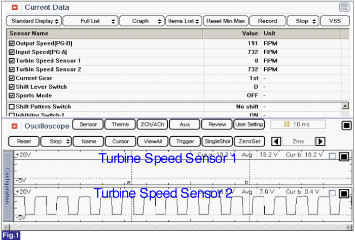
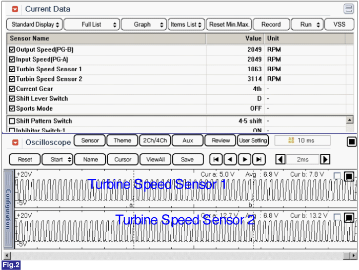
Fig 1) 1st gear in D range
Fig 2) 4th gear in D range
Singal waveform shows that voltage for Tubine Speed Sensor 1 & 2 is 0.5V or 13V when brake is ON
