
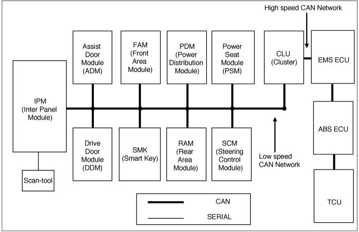
All 10 units which consists of the Body Electrical Control System are linked by CAN*¹ line.
They are IPM(Inter Panel Module), FAM(Front Area Module), PDM(Power Distribution Module),
DDM(Drive Door Module), ADM(Assist Door Module), CLU(Cluster), PSM(Power Seat Module),
SCM(Steering Control Module), RAM(Rear Area Module), SMK(Smart Key).
*¹ CAN (Controller Area Network) : CAN is serial bus communication type which links not only communication system but also control units each other
.*² LIN (Local Interconnect Network) : LIN is serial communication type which is used in electrical control system.
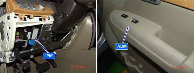
This is DTC which is related with communication error between IPM and other units.
(※ Control Units : IPM(Inter Panel Module), FAM(Front Area Module), PDM(Power Distribution Module), DDM(Drive Door Module), ADM(Assist Door Module), CLU(Cluster), PSM(Power Seat Module), SCM(Steering Control Module), RAM(Rear Area Module), SMK(Smart Key))
This DTC is set when Communication is not in normal status because CAN communication error or CAN hardware error is detected
Item | Detecting Condition | Possible Cause |
DTC Strategy |
•
CAN Communication Check |
•
Poor Connection in CAN high/low
•
CAN High and Low Line short to ground coincident
•
CAN High and Low Line short to battery coincident
•
Short circuit between CAN low and CAN high
•
Open in CAN low or high |
Enable Conditions |
•
Not in START position with IGN Key
•
200mS after START position with IGN Key | |
Threshold Value |
•
CAN high /low : 0 V or B+ | |
Diagnostic Time |
•
Immediately | |
DTC Erasing Time |
•
DTC is erased immediately after trouble fixed |
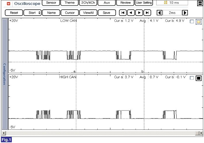
Fig 1) CAN Low/High Signal Waveform
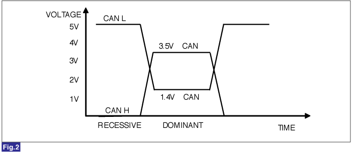
Fig 1) CAN BUS VOLTAGE LEVEL (LOW SPEED CAN)
