Disconnect the connectors (6P) from the actuator.
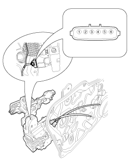
Remove the front door trim.
(Refer to the Body group - Front door)
Remove the front door module.
(Refer to the Body group - Front door)
Disconnect the connectors (6P) from the actuator.

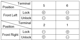
Check actuator operation by connecting power and ground according to the table. To prevent damage to the actuator, apply battery voltage only momentarily.
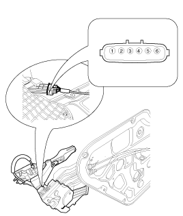
Remove the rear door trim.
(Refer to the Body group - Rear door)
Remove the rear door module.
(Refer to the Body group - Rear door)
Disconnect the connectors from the actuator.
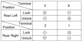
Check actuator operation by connecting power and ground according to the table. To prevent damage to the actuator, apply battery voltage only momentarily.
Remove the tailgate trim.
(Refer to the Body group - tailgate)
Disconnect the connector from the tailgate latch.
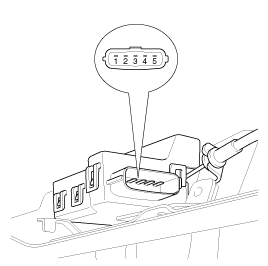
Check actuator operation by connecting power and ground according to the table. To prevent damage to the actuator, apply battery voltage only momentarily.
Remove the front door trim.
(Refer to the Body group - Front door)
Remove the front door module.
(Refer to the Body group - Front door)
Disconnect the connectors from the actuator.

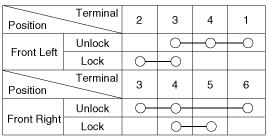
Check for continuity between the terminals in each switch position when inserting the key into the door according to the table.
Remove the rear door trim.
(Refer to the Body group - Rear door)
Remove the rear door module.
(Refer to the Body group - Rear door)
Disconnect the connectors from the actuator.

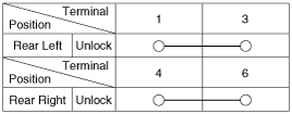
Check for continuity between the terminals in each switch position according to the table.
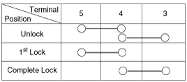
Remove the tailgate trim.
(Refer to the Body group - Tailgate)
Disconnect the connector from the tailgate latch.

Check for continuity between the terminals in each switch position according to the table.

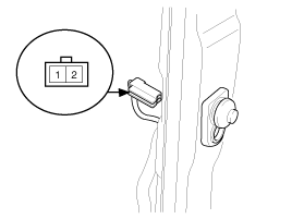
Remove the door switch and check for continuity between the terminals.

Disconnect the connector(A) from the hood switch.
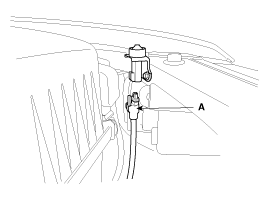
Check for continuity between the terminals and ground according to the table.

Remove the crash pad lower panel.
(Refer to Body group-Crash pad)
Disconnect the connector from the key warning switch(A).
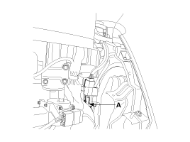
Check for continuity between the terminals in each position according to the table.

After loosening the mounting bolt(1EA) and disconnecting the horn connector, remove the burglar alarm horn.
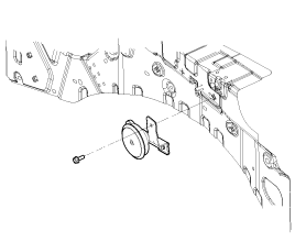
Check the continuity between the burglar alarm horn terminals when power is disconnected.