7.
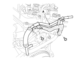
Remove the intercooler inlet hoses & pipe (A).
Tightening torque
Bolt :
19.6 ~ 26.4 N.m (2.0 ~ 2.7 kgf.m, 14.4 ~ 19.5 lb-ft)
Clamp :
4.9 ~ 6.8 N.m (0.5 ~ 0.7 kgf.m, 3.6 ~ 5.0 lb-ft)
Engine removal is not required for this procedure.
Use fender covers to avoid damaging painted surfaces.
To avoid damaging the cylinder head, wait until the engine coolant temperature drops below normal temperature before removing it.
When handling a metal gasket, take care not to fold the gasket or damage the contact surface of the gasket.
To avoid damage, unplug the wiring connectors carefully while holding the connector portion.
Mark all wiring and hoses to avoid misconnection.
Remove the engine cover.
Disconnect the battery negative terminal.
Remove the air duct and air cleaner assembly.
(Refer to Intake and Exhaust System - "Air Cleaner")
Remove the battery and battery tray.
(Refer to Engine Electrical System - "Battery")
Remove the engine room under cover.
(Refer to Engine And Transmission Assembly - "Engine Room Under Cover")
Loosen the drain plug and drain the coolant. Open the radiator cap to make rapid draining.
(Refer to Cooling System - "Coolant")
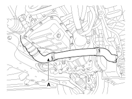
Remove the intercooler inlet hoses & pipe (A).
Tightening torque
Bolt :
19.6 ~ 26.4 N.m (2.0 ~ 2.7 kgf.m, 14.4 ~ 19.5 lb-ft)
Clamp :
4.9 ~ 6.8 N.m (0.5 ~ 0.7 kgf.m, 3.6 ~ 5.0 lb-ft)
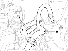
Remove the intercooler outlet hose (A).
Tightening torque:
4.9 ~ 6.8 N.m (0.5 ~ 0.7 kgf.m, 3.6 ~ 5.0 lb-ft)
Disconnect the radiator upper hose (B).
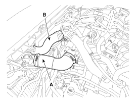
Disconnect the radiator lower hose (A).
Disconnect the engine wiring connector and haness clamp and then remove the cylinder head protector and wiring from engine.
Turbo charger solenoid valve connector
Exhuast OCV(Oil Control Valve) connector
Ignition connector # 1,2,3,4
FPCV(Fuel Pressure Control Valve) connector
Condenser connector
Exhuast CMPS(Cam position Sensor) connector
Intake CMPS(Cam Positoin Sensor) connector
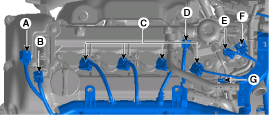
Injector Extension connector
PCSV(Purge Control Solenoid Valve) connector
Intake OCV(Oil Control Valve) connector
Alternator connector
A/C compressor switch connector
MAPS (Map Sensor) connector
Knock Sensor connector
Front connector
CKPS(Crank Shaft Position Sensor) connector
Vacuum Pump Extension connector
ETC(Electric Throttle Control) Module connector
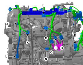
WTS(Water Temperature Sensor) connector
Ground Cable
Front Oxygen Sensor connector
Rear Oxygen Sensor connector
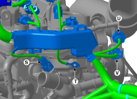
Disconnect the heater hoses (A) and brake booster vacuum hose(B).
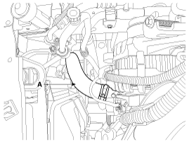
Remove the vaccum pipe assembly (A).
Remove the cylinder head cover.
(Refer to Cylinder Head Assembly - "Cylinder Head Cover")
Remove the timing chain cover.
(Refet to Timing System - "Timing Chain Cover")
Remove the timing chain.
(Refer to Timing System - "Timing Chain")
Remove the camshaft.
(Refer to Cylinder Head Assembly - "Camshaft")
Remove the intake manifold.
(Refer to Intake And Exhaust System - "Intake Manifold")
Remove the turbo manifold.
(Refer to Intake And Exhaust System - "Exhaust Manifold")
Remove the delivery pipe assembly.
(Refer to Engine Control / Fuel System - "Delivery Pipe")
Disconnect the bypass hose, and then remove the water temperature control assembly.
(Refer to Cooling System - "Water Temperature Control Assembly")
Remove the heater pipe.
(Refer to Cooling System - "Water Temperature Control Assembly")
Remove the intake OCV(Oil Control Valve).
(Refer to Engine Control / Fuel System - "CVVT Oil Control Valve")
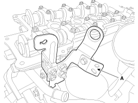
Remove the rear hanger (A).
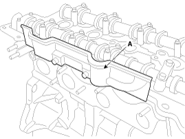
Remove the cylinder head cover heat protector (A).
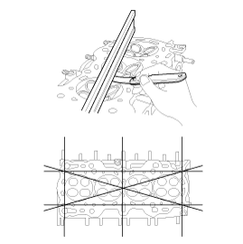
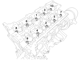
Remove the cylinder head bolts, then remove the cylinder head.
Uniformly loosen and remove the 10 cylinder head bolts, in several passes, in the sequence shown.
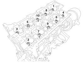
Head warpage or cracking could result from removing bolts in an incorrect order.
Lift the cylinder head from the cylinder block and put the cylinder head on wooden blocks.
Be careful not to damage the contact surfaces of the cylinder head and cylinder block.
Identify MLA(Mechanical lash adjuster), valves, valve springs as they are removed so that each item can be reinstalled in its original position.
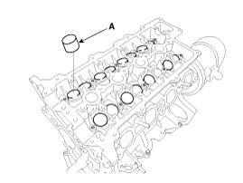
Remove the MLAs (A).
When removing MLAs, mark all the MLAs for their rearrangement.
Remove the valves.
Using the SST (09222 - 3K000, 09222 - 3K100), compress the valve spring and remove the retainer lock.

Remove the spring retainer.
Remove the spring.
Remove the valve.
Remove the valve stem seal.
Using a magnetic pickup tool, remove the spring seat.
Do not reuse the valve stem seals.
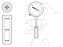
Inspect for flatness.
Using a precision straight edge and feeler gauge, measure the surface the contacting the cylinder block and the manifolds for warpage.
Flatness of cylinder head gasket surface
Standard :
Less than 0.05mm (0.0020in) for total area
Less than 0.02mm (0.0008in) for a section of 100mm (3.9370in) X 100mm (3.9370in)
Inspect for cracks.
Check the combustion chamber, intake ports, exhaust ports and cylinder block surface for cracks. If cracked, replace the cylinder head.
Inspect the valve stems and valve guides.
Using a caliper gauge, measure the inner diameter of valve guide.
Valve guide inner diameter :
5.500 ~ 5.512mm (0.2165 ~ 0.2170in)
Using a micrometer, measure the outer diameter of valve stem.
Valve stem outer diameter
Intake : 5.465 ~ 5.480mm (0.2152 ~ 0.2157in)
Exhaust : 5.458 ~ 5.470mm (0.2149 ~ 0.2154in)
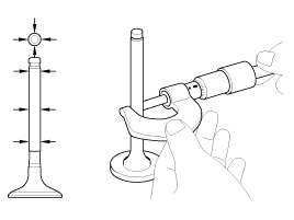
Subtract the valve stem outer diameter measurement from the valve guide inner diameter measurement.
Valve stem- to-guide clearance
Intake : 0.020 ~ 0.047mm (0.0008 ~ 0.0019in)
Exhaust : 0.030 ~ 0.054mm (0.0012 ~ 0.0021in)
If the clearance is greater than specification, replace the valve or the cylinder head.
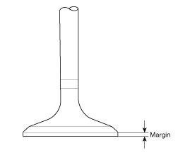
Inspect the valves.
Check the valve is ground to the correct valve face angle.
Check that the surface of valve for wear. If the valve face is worn, replace the valve.
Check the valve head margin thickness.
If the margin thickness is less than minimum, replace the valve.
Margin
Standard
Intake : 1.10mm (0.0433in)
Exhaust : 1.26mm (0.0496in)
Check the length of valve.
Valve length
Standard
Intake : 93.15mm (3.6673 in)
Exhaust : 92.60mm (3.6457 in)
Check the surface of valve stem tip for wear. If the valve stem tip is worn, replace the valve.
Inspect the valve seats.
Check the valve seat for evidence of overheating and improper contact with the valve face. If the valve seat is worn, replace the cylinder head.
Check the valve guide for wear. If the valve guide is worn, replace the cylinder head.
Inspect the valve springs.
Using a steel square, measure the out-of-square of valve spring.
Using a vernier calipers, measure the free length of valve spring.
Valve spring
Standard
Free height : 45.1mm (1.7756in)
Out of square : Less than 1.5˚
Thoroughly clean all parts to be assembled.
Before installing the parts, apply fresh engine oil to all sliding and rotating surface.
Replace oil seals with new ones.
Install the valves.
Install the spring seats.
Using the SST (09222 - 2B100), push in a new oil seal.
Do not reuse old valve stem oil seals.
Incorrect installation of the seal could result in oil leakage past the valve guides.
Intake valve stem seals are different from exhaust ones in type.
Do not reassembly ones in the other's places.
Install the valve, valve spring and spring retainer, after applying engine oil at the end of each valve.
When installing valve springs, the enamel coated side should face the valve spring retainer.
Using the SST(09222 - 3K000, 09222 - 3K100), compress the spring and install the retainer locks.
After installing the valves, ensure that the retainer locks are correctly in place before releasing the valve spring compressor.
When installing the SST, use the torque, 1.2kgf.m or less.
Lightly tap the end of each valve stem two or three times with the wooden handle of a hammer to ensure proper seating of the valve and retainer lock.
Install the MLA(Mechanical lash adjuster)s.
Check that the MLA (A) rotates smoothly by hand.
All the MLAs must be installed in its original position.
Thoroughly clean all parts to be assembled.
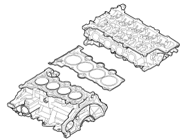
Always use a new cylinder head and manifold gasket.
Always use a new cylinder head bolt.
The cylinder head gasket is a metal gasket. Take care not to bend it.
Rotate the crankshaft, set the No.1 piston at TDC.
Install the cylinder head assembly.
Before installing, remove the hardened sealant from the cylinder block and cylinder head surface.
Before installing the cylinder head gasket, apply sealant on the upper surface of the cylinder block and reassemble the gasket within five minutes.
Refer to the illustration for applying sealant.
Width : 2.0 ~ 3.0mm(0.0787~0.1181in.)
Position : 1.0 ~ 1.5mm(0.0394~0.0591in.)
Specification : TB 1217H or LOCTITE 5900H
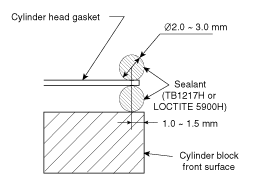
After installing the cylinder head gasket on the cylinder block, apply sealant on the upper surface of the cylinder head gasket and reassemble in five minutes.
Place the cylinder head carefully not to damage the gasket.
Install the cylinder head bolts with washers.
Tighten the 10 cylinder head bolts, in several passes, in the sequence shown.
Tightening torque :
29.4 N.m (3.0 kgf.m, 21.7 lb-ft) + 90° + 90°
Always use new cylinder head bolts.
Install the head cover heat protector (A).
Tightening torque :
9.8 ~ 11.8N.m (1.0 ~ 1.2kgf.m, 7.2 ~ 8.7lb-ft)
Install the rear hanger (A).
Install the oil control valve(OCV).
(Refer to Engine Control / Fuel System - "CVVT Oil Control Valve (OCV)")
Install the heater pipe.
(Refer to Cooling System - "Water Temperature Control Assembly")
Install the weter control assembly, and bypass hose.
(Refer to Cooling System - "Water Temperature Control Assembly")
Install the delivery pipe assembly.
(Refer to Engine Control / Fuel System - "Delivery Pipe")
Install the intake manifold.
(Refer to Intake And Exhaust System - "Intake Manifold")
Install the turbo manifold.
(Refer to Intake And Exhaust System - "Exhaust Manifold")
Install the cam shaft.
(Refer to Cylinder Head Assembly - "Cam Shaft")
Install the timing chain.
(Refer to Timing System - "Timing Chain")
Install the timing chain cover.
(Refer to Timing System - "Timing Chain Cover)
Install the cylinder head cover.
(Refer to Cylinder Head Assembly - "Cylinder Head Cover")
Do not reuse the disassembled gasket.
Install the vacuum pipe assembly (A).
Tightening torque :
9.8 ~ 11.8N.m (1.0 ~ 1.2kgf.m, 7.2 ~ 8.7lb-ft)
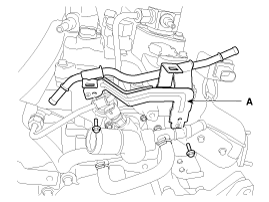
Connect the heater hoses (A) and brake booster vacuum hose (B).
Install in the reverse order of removal.
Perform the following :
Refill engine with engine oil.
Refill a radiator and a reservoir tank with engine coolant.
Inspect for fuel leakage.
After assemble the fuel line, turn on the ignition switch (do not operate the starter) so that the fuel pump runs for approximately two seconds and fuel line pressurizes.
Repeat this operation two or three times, then check for fuel leakage at any point in the fuel line.
Bleed air from the cooling system.
Start engine and let it run until it warms up. (until the radiator fan operates 3 or 4 times.)
Turn Off the engine. Check the level in the radiator, add coolant if needed. This will allow trapped air to be removed from the cooling system.
Put radiator cap on tightly, then run the engine again and check for leaks.
