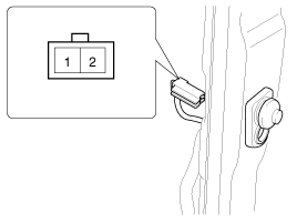
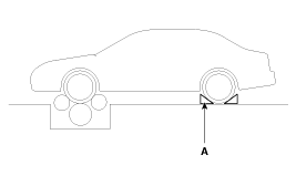
Inspection
Speedometer
1.

Adjust the pressure of the tires to the specified level.

2.

Drive the vehicle onto a speedometer tester. Use wheel chocks (A) as appropriate.

3.

Check if the speedometer indicator range is within the standard values.

caution

Do not operate the clutch suddenly or increase/ decrease speed rapidly while testing.

note

Tire wear and tire over or under inflation will increase the indication error.

[km/h]

Velocity(Km/h)

Tolerance(Km/h)

20

+3.0

+0.5

40

+5.8

+3.3

60

+6.2

+3.7

80

+7.1

+4.1

100

+7.5

+4.5

120

+7.9

+4.9

140

+9.4

+5.9

160

+10.4

+6.9

180

+11.4

+7.9

200

+12.4

+8.9

220

+13.4

+9.9

240

+14.4

+10.9

[mph]

Velocity(mph)

Tolerance(mph)

20

+3.0

+1.0

40

+4.9

+2.9

60

+6.8

+4.8

80

+7.5

+5.0

100

+8.2

+5.2

120

+8.7

+5.7

140

+9.2

+6.2

160

-

Tachometer
1.

Connect the GDS to the diagnostic link connector or install a tachometer.

2.

With the engine started, compare the readings of the tester with that of the tachometer. Replace the tachometer if the tolerance is exceeded.

caution
1.

Reversing the connections of the tachometer will damage the transistor and diodes inside.

2.

When removing or installing the tachometer, be careful not to drop it or subject it to severe shock.

Revolution

(rpm)

Gasoline

Diesel

Tolerance (rpm)

Max 8,000 rpm

Tolerance (rpm)

Max 6,000 rpm

1,000

± 100

± 100

2,000

± 100

± 100

3,000

± 100

± 100

4,000

± 100

± 100

5,000

± 100

± 100

6,000

± 100

± 100

7,000

± 100


8,000

± 100

Fuel Gauge
1.

Disconnect the fuel sender connector from the fuel sender.

2.

Remove the fuel pump assembly.

3.

Check motor operation by fuel pump connector (A) connecting power (No.4) and ground (No.5).

No.

Description

1

Fuel sender signal

2

 - 

3

Fuel sender ground

4

-

5

Fuel pump motor (+)

6

Fuel pump motor (-)

Main Fuel Gauge Sender
1.

Turn the ignition switch OFF, and then remove battery (-) cable.

2.

Remove the fuel pump assembly.

3.

Using an ohmmeter, measure the resistance between terminals 1 and 3 of sender connector (A) at each float level.

No.

Description

1

Fuel sender signal

2

 - 

3

Fuel sender ground

4

-

5

Fuel pump motor (+)

6

Fuel pump motor (-)

4.

Also check that the resistance changes smoothly when the float is moved from "E" to "F".

Position

Resistance(Ω)

Capacity (ℓ)

E

197 ~ 203

3.7

 1/2

64.2 ~ 68.2

26.7

Sender (F)

6 ~ 10

52.6

5.

If the height resistance is unsatisfied, replace the fuel sender as an assembly.

caution

After completing this test, wipe the sender dry and reinstall it in the fuel tank.

Brake Fluid Level Warning Switch
1.

Remove the connector (A) from the switch located at the brake fluid reservoir.

2.

Verify that continuity exists between switch terminals 1 and 2 while pressing the switch (float) down with a rod.

Brake Fluid Level Warning Lamp
1.

Ignition "ON"

2.

Release the parking brake.

3.

Remove the connector from the brake fluid level warning switch.

4.

Ground the connector at the harness side.

5.

Verify that the warning lamp lights.

Parking Brake Switch

The parking brake switch (A) is a pulling type. It is located under the parking brake lever. To adjust, move the switch mount up and down with the parking brake lever released all the way.

1.

Check that there is continuity between the terminal and switch body with the switch ON (Lever is pulled).

2.

Check that there is no continuity between the terminal and switch body with the switch OFF (Lever is released).

If continuity is not as specified, replace the switch or inspect its ground connection.

Door Switch

Remove the door switch and check for continuity between the terminals.

Seat Belt Switch
1.

Remove the connector from the switch.

2.

Check for continuity between terminals.

Seat belt condition

Continuity

Fastened

Non-conductive (∞Ω)

Not fastened

Conductive (Ω)

Seat Belt Warning Lamp

With the ignition switch turned ON, verify that the lamp glows.

Seat belt condition

Warning lamp

Fastened

OFF

Not fastened

ON

Diagnosis with GDS
1.

It will be able to diagnose defects of CLU with GDS quickly. GDS can operates actuator forcefully, input/output value monitoring and self diagnosis.

2.

Select model and "BCM".

3.

Select the "Cluster Moduel" to check.

4.

Select "Input/output monitoring", if you will check current data of instrument cluster.

5.

If you will check each module data operation forcefully, select "Actuation test".

6.

To check the DTC of the each module, select "DIAGNOSTIC TROUBLE CODES".

CLU Variant Coding

After replacing the cluster with a new one, must be performed the “Variant Coding” procedure.

1.

Connect the cable of GDS to the data link connector in driver side crash pad lower panel, turn the power on GDS.

2.

Select model and "BCM".

3.

Select Variant coding mode to perform.

4.

If the trouble codes occurred when performing variant coding, try the CLU variant coding again after checking the installation status of CLU system.

Яндекс.Метрика