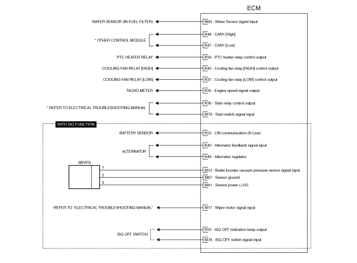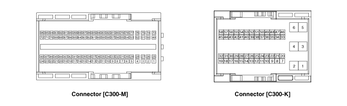
Pin | Description | Connected to |
1 | - |
|
2 | - |
|
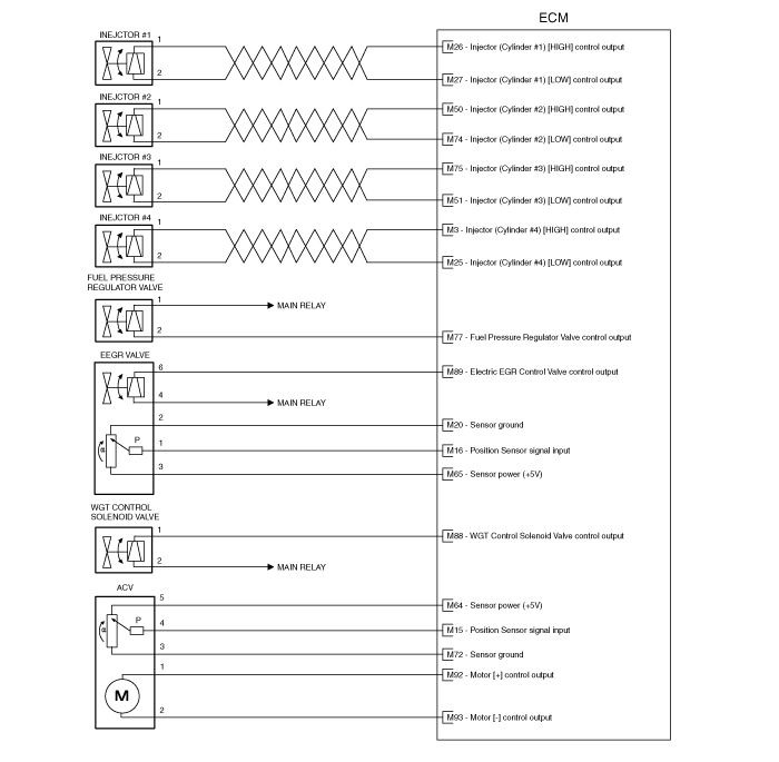
3 | Injector (Cylinder #4) [High] control output | Injector (Cylinder #4) |
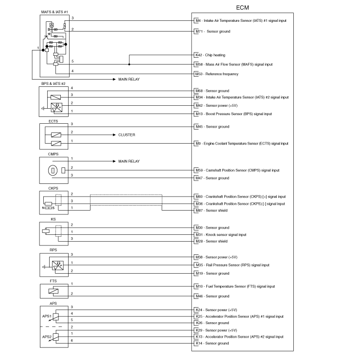
4 | Intake Air Temperature Sensor (IATS) #1 signal input | Intake Air Temperature Sensor (IATS) #1 [MAFS] |
5 | Exhaust Gas Temperature Sensor (EGTS) #1 signal input | Exhaust Gas Temperature Sensor (EGTS) #1 [With DPF] |
6 | Exhaust Gas Temperature Sensor (EGTS) #2 signal input | Exhaust Gas Temperature Sensor (EGTS) #2 [With DPF] |
7 | Power ground | Chassis ground |
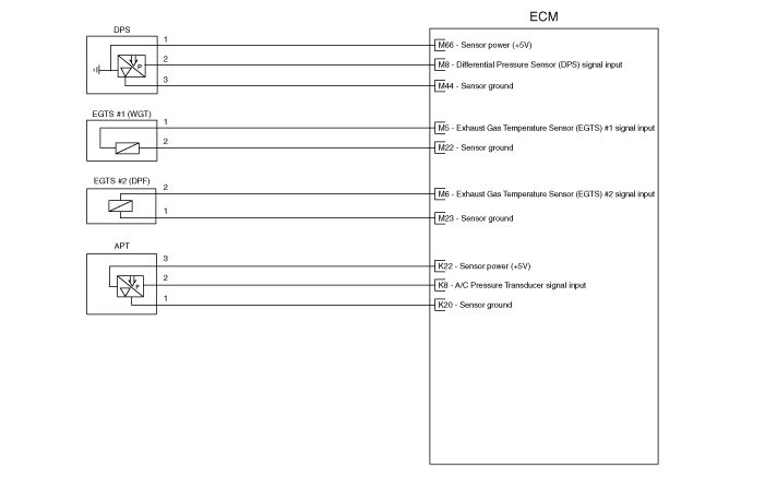
8 | Differential Pressure Sensor (DPS) signal input | Differential Pressure Sensor (DPS) [With DPF] |
9 | Engine Coolant Temperature Sensor (ECTS) signal input | Engine Coolant Temperature Sensor (ECTS) |
10 | Fuel Temperature Sensor (FTS) signal input | Fuel Temperature Sensor (FTS) |
11 | - | |
12 | Brake Booster Vacuum Pressure Sensor signal input | Brake Booster Vacuum Pressure Sensor [With ISG] |
13 | Boost Pressure Sensor (BPS) signal input | Boost Pressure Sensor (BPS) |
14 | - |
|
15 | Position sensor signal input | Position Sensor in Air Control Valve (ACV) [With DPF] |
16 | Position sensor signal input | Position Senor in Electric EGR Control Valve |
17 | Wiper motor signal input | Wiper motor [with ISG] |
18 | - |
|
19 | Sensor ground | Rail Pressure Sensor (RPS) |
20 | Sensor ground | Position Senor in Electric EGR Control Valve |
21 | - |
|
22 | Sensor ground | Exhaust Gas Temperature Sensor (EGTS) #1 [With DPF] |
23 | Sensor ground | Exhaust Gas Temperature Sensor (EGTS) #2 [With DPF] |
24 | - |
|
25 | Injector (Cylinder #4) [Low] control output | Injector (Cylinder #4) |
26 | Injector (Cylinder #1) [High] control output | Injector (Cylinder #1) |
27 | Injector (Cylinder #1) [Low] control output | Injector (Cylinder #1) |
28 | Sensor shield | Knock Senor (KS) |
29 | - |
|
30 | Sensor ground | Knock Senor (KS) |
31 | Knock Senor (KS) signal input | Knock Senor (KS) |
32 | - |
|
33 | - |
|
34 | Intake Air Temperature Sensor (IATS) #2 signal input | Intake Air Temperature Sensor (IATS) #2 [integrated into BPS module] |
35 | Rail Pressure Sensor (RPS) signal input | Rail Pressure Sensor (RPS) |
36 | Crankshaft Position Sensor (CKPS) [-] signal input | Crankshaft Position Sensor (CKPS) |
37 | - |
|
38 | Sensor power (+5V) | Rail Pressure Sensor (RPS) |
39 | - |
|
40 | - |
|
41 | Sensor power (+5V) | Brake Booster Vacuum Pressure Sensor [With ISG] |
42 | Sensor power (+5V) | Boost Pressure Sensor (BPS) |
43 | - | |
44 | Sensor ground | Differential Pressure Sensor (DPS) [With DPF] |
45 | Sensor ground | Engine Coolant Temperature Sensor (ECTS) |
46 | Sensor ground | Fuel Temperature Sensor (FTS) |
47 | Sensor ground | Camshaft Position Sensor (CMPS) |
48 | - |
|
49 | - |
|
50 | Injector (Cylinder #2) [High] control output | Injector (Cylinder #2) |
51 | Injector (Cylinder #3) [High] control output | Injector (Cylinder #3) |
52 | Neutral Switch signal input | Neutral Switch |
53 | Reference frequency | Mass Air Flow Sensor (MAFS) |
54 | - |
|
55 | - |
|
56 | - |
|
57 | - |
|
58 | Mass Air Flow Sensor (MAFS) signal input | Mass Air Flow Sensor (MAFS) |
59 | Camshaft Position Sensor (CMPS) signal input | Camshaft Position Sensor (CMPS) |
60 | Crankshaft Position Sensor (CKPS) [+] signal input | Crankshaft Position Sensor (CKPS) |
61 | - |
|
62 | - |
|
63 | - |
|
64 | Sensor power (+5V) | Position Sensor in Air Control Valve (ACV) [With DPF] |
65 | Sensor power (+5V) | Position Senor in Electric EGR Control Valve |
66 | Sensor power (+5V) | Differential Pressure Sensor (DPS) [With DPF] |
67 | Sensor ground | Brake Booster Vacuum Pressure Sensor [With ISG] |
68 | Sensor ground | Boost Pressure Sensor (BPS) |
69 | - |
|
70 | - |
|
71 | Sensor ground | Mass Air Flow Sensor (MAFS) |
72 | Position sensor ground | Position Sensor in Air Control Valve (ACV) [With DPF] |
73 | - |
|
74 | Injector (Cylinder #2) [Low] control output | Injector (Cylinder #2) |
75 | Injector (Cylinder #3) [Low] control output | Injector (Cylinder #3) |
76 | - |
|
77 | Fuel Pressure Regulator Valve control output | Fuel Pressure Regulator Valve |
78 | ISG OFF switch input | ISG OFF switch |
79 | Start Switch Input | Ignition swich |
80 | - |
|
81 | - |
|
82 | - |
|
83 | - |
|
84 | - |
|
85 | Glow Relay control output | Glow Relay |
86 | - |
|
87 | Sensor shield | Crankshaft Position Sensor (CKPS) |
88 | WGT Control Solenoid Valve control output | WGT Control Solenoid Valve |
89 | Electric EGR Control Valve control output | Electric EGR Control Valve |
90 | - |
|
91 | - |
|
92 | Motor [+] control output | Air Control Valve (ACV) [With DPF] |
93 | Motor [-] control output | Air Control Valve (ACV) [With DPF] |
94 | - | |
95 | Water Sensor signal input | Water Sensor [Fuel filter] |
96 | - |
Pin | Description | Connected to |
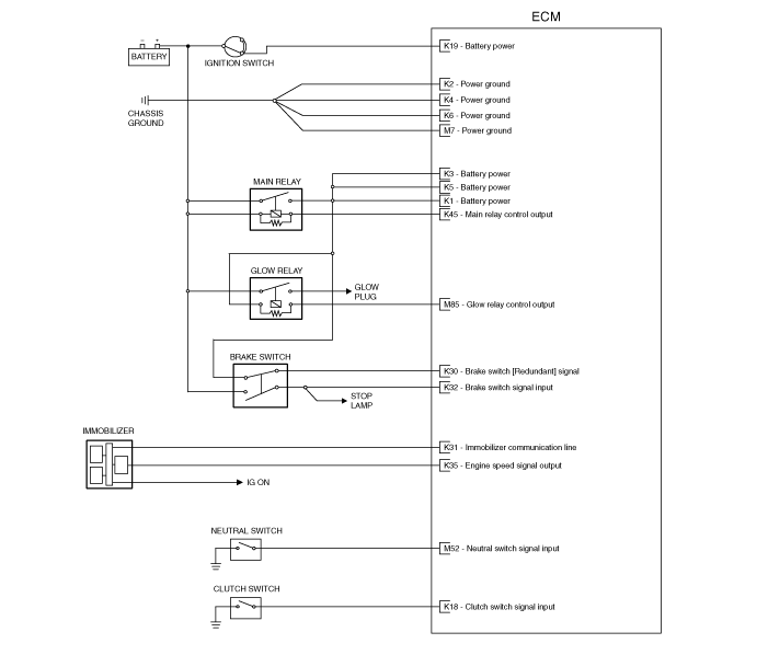
1 | Battery power | Main Relay |
2 | Power ground | Chassis ground |
3 | Battery power | Main Relay |
4 | Power ground | Chassis ground |
5 | Battery power | Main Relay |
6 | Power ground | Chassis ground |
7 | - | |
8 | A/C Pressure Transducer (APT) signal input | A/C Pressure Transducer (APT) |
9 | - |
|
10 | - |
|
11 | - |
|
12 | - |
|
13 | Accelerator Position Sensor (APS) #2 signal input | Accelerator Position Sensor (APS) #2 |
14 | Sensor ground | Accelerator Position Sensor (APS) #2 |
15 | - | |
16 | - | |
17 | - | |
18 | Clutch Top Switch signal input | Clutch switch |
19 | Battery power | Ignition Switch |
20 | Sensor ground | A/C Pressure Transducer (APT) |
21 | - |
|
22 | Sensor power (+5V) | A/C Pressure Transducer (APT) |
23 | - |
|
24 | Sensor power (+5V) | Accelerator Position Sensor (APS) #1 |
25 | Accelerator Position Sensor (APS) #1 signal input | Accelerator Position Sensor (APS) #1 |
26 | Sensor ground | Accelerator Position Sensor (APS) #1 |
27 | Vehicle Speed Sensor (VSS) signal input | Vehicle Speed Sensor (VSS) |
28 | - | |
29 | Sensor power (+5V) | Accelerator Position Sensor (APS) #2 |
30 | Brake [Redundant] switch signal input | Brake switch |
31 | Immobilizer signal | Immobilizer Control Module |
32 | Brake [Main] switch signal input | Brake switch |
33 | - | |
34 | - |
|
35 | Engine speed signal output | Tacho meter |
36 | Starter relay control output | Starter relay |
37 | Cooling Fan Relay [Low] control output | Cooling Fan Relay [Low] |
38 | - | |
39 | - | |
40 | Alternator Regulator Feedback | Alternator |
41 | - | |
42 | Chip heating | Mass Air Flow Sensor (MAFS) |
43 | Cooling Fan Relay [High] control output | Cooling Fan Relay [High] |
44 | - |
|
45 | Battery power | Main Relay |
46 | - | |
47 | CAN 1 [Low] | Other control module |
48 | CAN 1 [High] | Other control module |
49 | Alternator Regulator Output | Alternator |
50 | ISG Indication Lamp control output | ISG OFF switch |
51 | - | |
52 | LIN communication (K-Line) | Battery Sensor |
53 | CCP-CAN (High) | |
54 | CCP-CAN (Low) | |
55 | - | |
56 | PTC Heater Relay output | PTC Heater Relay |
57 | - |
|
58 | - |
Pin | Pin description | Vehicle state | Signal type | Reference level | Test result |
1 | - |
|
|
|
|
2 | - |
|
|
|
|
3 | Injector (Cylinder #4) [High] control output | Idle | Pulse | Battery Voltage ~ 75V |
|
4 | Intake Air Temperature Sensor (IATS) #1 signal input | Idle | Analog | 0.244 ~ 4.760V | 2.11V / 33.5degC |
5 | Exhaust Gas Temperature Sensor (EGTS) #1 signal input | Idle | Analog | 0.409 ~ 4.987V | 4.98V / 130degC |
6 | Exhaust Gas Temperature Sensor (EGTS) #2 signal input | Idle | Analog | 0.409 ~ 4.987V | 4.98V / 130degC |
7 | Power ground | Ignition ON | DC | 0 ~ 0.6V | 0.007V |
8 | Differential Pressure Sensor (DPS) signal input | Idle | Analog | 1 ~ 4.5V | 1.007V / 0.31kPa |
9 | Engine Coolant Temperature Sensor (ECTS) signal input | Idle | Analog | 0.195 ~ 4.849V | 2.72V / 28.5degC |
10 | Fuel Temperature Sensor (FTS) signal input | Idle | Analog | 0.132 ~ 4.995V | 3.03V / 24.5degC |
11 | - |
|
|
|
|
12 | Brake Booster Vacuum Pressure Sensor signal input | Idle | Analog | 0.3 ~ 4.8V | 4.17V / 860 cnt (full vac) 0.47V / 98 cnt (no vac) |
13 | Boost Pressure Sensor (BPS) signal input | Idle | Analog | 0.5 ~ 4.5V | 1.60V / 1.01Bar |
14 | - | Ignition ON | DC | 0.2273 V +/-0.1V 4.5 V +/-0.1V |
|
15 | Sensor ground | Idle | Analog | 0.15 ~ 4.9V | 4.37V / 100% |
16 | Position sensor signal input | Idle | Analog | 0.15 ~ 4.9V | 0.78V / 42.31% |
17 | Wiper motor signal input |
|
|
|
|
18 | - |
|
|
|
|
19 | Sensor ground | Ignition ON | DC | 0 ~ 0.3 V | 0.007V |
20 | Sensor ground |
|
|
|
|
21 | - |
|
|
|
|
22 | Sensor ground | Ignition ON | DC | 0 ~ 0.3 V | 0.007V |
23 | Sensor ground | Ignition ON | DC | 0 ~ 0.3 V | 0.007V |
24 | - |
|
|
|
|
25 | Injector (Cylinder #4) [Low] control output | Idle | Pulse | High : Battery Voltage ~ 75V Low : Max. 1.0V |
|
26 | Injector (Cylinder #1) [High] control output | Idle | Pulse | Battery Voltage ~ 75V |
|
27 | Injector (Cylinder #1) [Low] control output | Idle | Pulse | High : Battery Voltage ~ 75V Low : Max. 1.0V |
|
28 | Sensor shield | Ignition ON | DC | 0 ~ 0.3 V | 0.007V |
29 | - |
|
|
|
|
30 | Sensor ground | Idle |
|
|
|
31 | Knock Senor (KS) signal input | Idle |
|
|
|
32 | - |
|
|
|
|
33 | - |
|
|
|
|
34 | Intake Air Temperature Sensor (IATS) #2 signal input | Idle | Analog | 0.391 ~ 4.907V | 3.3V / 25degC |
35 | Rail Pressure Sensor (RPS) signal input | Idle | Analog | 0.5 ~ 4.5V | 0.505V / 7bar |
36 | Crankshaft Position Sensor (CKPS) [-] signal input | Idle | Sine Wave | Vp_p : Min. 1.0V Max. 360V |
|
37 | - |
|
|
|
|
38 | Sensor power (+5V) | Ignition ON | DC | 4.7 ~ 5.1 V | 5V |
39 | - |
|
|
|
|
40 | - |
|
|
|
|
41 | Sensor power (+5V) | Ignition ON | DC | 4.7 ~ 5.1 V | 5V |
42 | Sensor power (+5V) | Ignition ON | DC | 4.7 ~ 5.1 V | 5V |
43 | - | ||||
44 | Sensor ground | Ignition ON | DC | 0 ~ 0.3 V | 0.007V |
45 | Sensor ground | Ignition ON | DC | 0 ~ 0.3 V | 0.007V |
46 | Sensor ground | Ignition ON | DC | 0 ~ 0.3 V | 0.007V |
47 | Sensor ground | Ignition ON | DC | 0 ~ 0.3 V | 0.007V |
48 | - |
|
|
|
|
49 | - |
|
|
|
|
50 | Injector (Cylinder #2) [High] control output | Idle | Pulse | Battery Voltage ~ 75V |
|
51 | Injector (Cylinder #3) [Low] control output | Idle | Pulse | High : Battery voltage ~ 75V Low : Max 1.0V |
|
52 | Neutral Switch signal input | Neural Gear engaged | DC | Vbatt Max 0.3 V | 10.8V 0.006V |
53 | Reference frequency | Idle | Pulse | 16.7~25Hz High : Vcc Low : Max 0.7V | 19.08Hz / 52ms |
54 | - |
|
|
|
|
55 | - |
|
|
|
|
56 | - |
|
|
|
|
57 | - |
|
|
|
|
58 | Mass Air Flow Sensor (MAFS) signal input | Idle | Pulse | 1.2~14kHz High : Vcc Low : Max 0.7V | 2273Hz/7.0g/s |
59 | Camshaft Position Sensor (CMPS) signal input | Idle | Pulse | High : Battery voltage ~ 0.8V (Max. 24V) Low : Max. 0.5V |
|
60 | Crankshaft Position Sensor (CKPS) [+] signal input | Idle | Sine Wave | Vp_p : Min. 1.0V Max. 360V |
|
61 | - |
|
|
|
|
62 | - | Ignition ON | DC | 4.7 ~ 5.1 V |
|
63 | - |
|
|
|
|
64 | Sensor power (+5V) | Ignition ON | DC | 4.7 ~ 5.1 V | 5V |
65 | Sensor power (+5V) | Ignition ON | DC | 0 ~ 0.3 V | 0.007V |
66 | Sensor power (+5V) | Ignition ON | DC | 4.7 ~ 5.1 V | 5V |
67 | Sensor ground | Ignition ON | DC | 0 ~ 0.3 V | 0.007V |
68 | Sensor ground | Ignition ON | DC | 0 ~ 0.3 V | 0.007V |
69 | - | Ignition ON | DC | 0 ~ 0.3 V |
|
70 | - |
|
|
|
|
71 | Sensor ground | Ignition ON | DC | 0 ~ 0.3 V | 0.12V |
72 | Position sensor ground | Ignition ON | DC | 0 ~ 0.3 V | 0.007V |
73 | - |
|
|
|
|
74 | Injector (Cylinder #2) [Low] control output | Idle | Pulse | High : Battery Voltage ~ 75V Low : Max. 1.0V |
|
75 | Injector (Cylinder #3) [High] control output | Idle | Pulse | Battery Voltage ~ 75V |
|
76 | - |
|
|
|
|
77 | Fuel Pressure Regulator Valve control output | Idle | Pulse | Vbatt Ground : Max. 0.3V | 350Hz / 40% |
78 | ISG OFF switch input | Switch Off Switch On | DC | Vbatt Max 0.3 V |
|
79 | Start Switch Input | Key On Key Start | DC | Max 0.3 V Vbatt | 0.005V 12.8V |
80 | - |
|
|
|
|
81 | - |
| |||
82 | - |
|
|
|
|
83 | - | Ignition ON | PWM Positive Freq. 1000 Hz | Vbatt Ground |
|
84 | - | ||||
85 | Glow Relay control output | Relay OFF Relay ON | DC | Vbatt Max 0.7 V | 12.12V 0.1V |
86 | - |
|
|
|
|
87 | Sensor shield | Ignition ON | DC | 0 ~ 0.3 V | 0.004V |
88 | WGT Control Solenoid Valve control output | Idle | Pulse | Vbatt Ground : Max. 0.3V | 300Hz / 28% |
89 | Electric EGR Control Valve control output | Idle | Pulse | Vbatt Ground : Max. 0.3V | 140Hz / 10% |
90 | - |
|
|
|
|
91 | - |
|
|
|
|
92 | Motor [+] control output | Idle | Pulse | Vbatt Ground : Max. 0.3V | 1000Hz / 16% (neg) |
93 | Motor [-] control output | ||||
94 | - | ||||
95 | Water Sensor signal input | Water in Fuel No water | DC | Vbatt Max 0.3 V | - 0.005V |
96 | - |
Pin | Pin description | Vehicle state | Signal type | Reference level | Test result |
1 | Battery power | Ignition ON | DC | Vbatt | 12.05V |
2 | Power ground | Ignition ON | DC (Engine) | 0 ~ 0.3 V | 0V |
3 | Battery power | Ignition ON | DC | Vbatt | 12.05V |
4 | Power ground | Ignition ON | DC (Engine) | 0 ~ 0.3 V | 0V |
5 | Battery power | Ignition ON | DC | Vbatt | 12.05V |
6 | Power ground | Ignition ON | DC (Engine) | 0 ~ 0.3 V | 0V |
7 | - |
|
|
|
|
8 | A/C Pressure Transducer (APT) signal input | Idle | Analog | 0.5 ~ 4.5V | 1.23 V / 5.75bar |
9 | - |
|
|
|
|
10 | - |
|
|
|
|
11 | - |
|
|
|
|
12 | - |
|
|
|
|
13 | Accelerator Position Sensor (APS) #2 signal input | C.T W.O.T | Analog | 0.275 ~ 0.475 V 1.9 ~ 2.2 V | 0.373V / 0% 2.04V / 100% |
14 | Sensor ground | Ignition ON | DC | 0 ~ 0.3 V | 0.009V |
15 | - |
| |||
16 | - | ||||
17 | - | ||||
18 | Clutch Top Switch signal input | Push Release | DC | Vbatt Max 1.5 V | 11.21V 0.002V |
19 | Battery power | Key OFF Key ON | DC | Max 2 V Vbatt | 0.23V 12.02V |
20 | Sensor ground | Ignition ON | DC | 0 ~ 0.3 V | 0.008V |
21 | - |
|
|
|
|
22 | Sensor power (+5V) | Ignition ON | DC | 4.7 ~ 5.1 V | 5V |
23 | - |
|
|
|
|
24 | Sensor power (+5V) | Ignition ON | DC | 4.7 ~ 5.1 V | 5V |
25 | Accelerator Position Sensor (APS) #1 signal input | C.T W.O.T | Analog | 0.7 ~ 0.85 V 3.95 ~ 4.25 V | 0.737V 4.04V |
26 | Sensor ground | Ignition ON | DC | 0 ~ 0.3 V | 0.009V |
27 | - |
| |||
28 | - | ||||
29 | Sensor power (+5V) | Ignition ON | DC | 4.7 ~ 5.1 V | 5V |
30 | Brake [Redundant] switch signal input | Push Release | DC | Max 1.5 V Vbatt | 0.005V 12.2V |
31 | Immobilizer signal | Ignition ON |
|
| OK |
32 | Brake [Main] switch signal input | Push Release | DC | Vbatt Max 1.5 V | 11.62V 0.005V |
33 | - |
| |||
34 | - |
|
|
|
|
35 | Engine speed signal output | Idle | Pulse | 1 rpm = 0.0666Hz High : Min Vbatt - 1.23V Low : Max 1.1V | 54.35Hz / 849rpm |
36 | Starter relay control output | Relay OFF Relay ON | DC | Vbatt Max 1.5 V | 12V 0.002V |
37 | Cooling Fan Relay [Low] control output | Relay OFF Relay ON | DC | Vbatt Max 0.7 V | 12V 0.018V |
38 | - | ||||
39 | - | ||||
40 | Alternator Regulator Feedback | Idle | Pulse | High : Min 3V Low : Max 1.5V |
|
41 | - | ||||
42 | Chip heating |
|
|
|
|
43 | Cooling Fan Relay [High] control output | Relay OFF Relay ON | DC | Vbatt Max 0.7 V | 12V 0.02V |
44 | - |
|
|
|
|
45 | Battery power | Relay OFF Relay ON | DC | Max 1.2 V Vbatt | 0.9V 12V |
46 | - |
| |||
47 | CAN 1 [Low] | RECESSIVE DOMINANT | Pulse | 2.0 ~ 3.0V 0.5 ∼ 2.25V |
|
48 | CAN 1 [High] | RECESSIVE DOMINANT | Pulse | 2.0 ~ 3.0V 2.75 ∼ 4.5V |
|
49 | Alternator Regulator Output | Idle | Pulse | High : Min 4V Low : Max 2V |
|
50 | ISG Indication Lamp control output |
|
|
|
|
51 | - | ||||
52 | LIN communication (K-Line) | Ignition ON |
|
| OK |
53 | CCP-CAN (High) |
|
|
|
|
54 | CCP-CAN (Low) |
|
|
|
|
55 | Malfunction Indication Lamp (MIL) control output | ||||
56 | PTC Heater Relay output | Relay OFF Relay ON | DC | Vbatt Max 0.4 V | 12V 0.02V |
57 | - |
|
|
|
|
58 | - |