Removal

Engine removal is not required for this procedure.

caution

Use fender covers to avoid damaging painted surfaces.

To avoid damage, unplug the wiring connectors carefully while holding the connector portion.

note

Mark all wiring and hoses to avoid misconnection.

1.

Remove the engine cover.

2.

Disconnect the battery negative terminal.

Tightening torque :

4.0 ~ 6.0N.m (0.4 ~ 0.6kgf.m, 3.0 ~ 4.4lb-ft)

3.

Disconnect the breather hose.

(Refer to Intake And Exhaust System - "Air Cleaner")

4.

Remove the RH front wheel.

5.

Remove the under cover.

6.

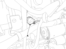
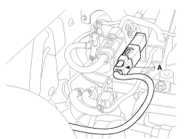
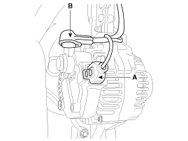
Disconnect the engine wiring harness connectors and remove the wiring harness protectors.

<a href="content.asp?vehicletype=Passenger&mfrcode=KM&area=KME&langcode=ENG&modelid=JD12&modelyr=2013&mmctype=en&mmcid=349&group=SHOP&pdftype=&cat1=2013+%3E+D+1%2E4+TCI%2DU2&firstnodedesc=Fuel+System&sitinfolist=14%5E1420%5Enone%5Enone%5E401%5E2%5EENG%5EKM%5EJD12%5E2013%5Een%5E349%5Enone%5Enone%5Enone%5ESHOP%5E%24" target="_blank"> (U-II 1.4L : Refer to Fuel System – “Engine Control System”)</a>

<a href="content.asp?vehicletype=Passenger&mfrcode=KM&area=KME&langcode=ENG&modelid=JD12&modelyr=2013&mmctype=en&mmcid=348&group=SHOP&pdftype=&cat1=2013+%3E+D+1%2E6+TCI%2DU2&firstnodedesc=Fuel+System&sitinfolist=14%5E1420%5Enone%5Enone%5E401%5E2%5EENG%5EKM%5EJD12%5E2013%5Een%5E348%5Enone%5Enone%5Enone%5ESHOP%5E%24" target="_blank">(U-II 1.6L : Refer to Fuel System – “Engine Control System”)</a>

(1)

Variable swirl control actuator connector

(2)

Fuel pressure regulator valve connector

(3)

Fuel temperature sensor connector

(4)

Oil pressure switch connector (A)

(5)

VGT control solenoid valve connector

(6)

Crankshaft position sensor (CKPS) connector

(7)

Air control valve connector

(8)

Injector connectors

(9)

Cam position sensor (CMPS) connector

(10)

Electric EGR control valve connector

(11)

Glow plug connector (A)

(12)

Exhaust gas temperature sensor (#1, #2) connectors

(13)

Difference pressure sensor connector

(14)

Lambda sensor connector (1.6L only)

(15)

Alternator connector (A) and the cable (B)

Tightening torque

Cable (B):

9.8 ~ 14.7N.m (1.0 ~ 1.5kgf.m, 7.2 ~ 10.8lb-ft)
7.

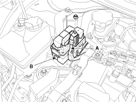
Disconnect the wiring (A) and then remove the fuse/relay box (B).

8.

Remove the cylinder head cover.

(Refer to Cylinder Head Assembly – “Cylinder Head Cover”)

9.

Remove the drive belt.

(Refer to Timing System – “Drive Belt”)

10.

Set the jack to the engine oil pan.

11.

Remove the engine mounting bracket.

(Refer to Engine And Transaxle Assembly – “Engine Mounting”)

12.

Drain the engine oil and then remove the oil filter & cooler assembly.

(Refer to Lubrication system – “Oil Filter & Cooler Assembly”)

13.

Remove the alternator.

<a href="content.asp?vehicletype=Passenger&mfrcode=KM&area=KME&langcode=ENG&modelid=JD12&modelyr=2013&mmctype=en&mmcid=348&group=SHOP&pdftype=&cat1=2013+%3E+D+1%2E6+TCI%2DU2&firstnodedesc=Engine+Electrical+System&sitinfolist=11%5E1125%5E11250100%5Enone%5E801%5E1%5EENG%5EKM%5EJD12%5E2013%5Een%5E348%5Enone%5Enone%5Enone%5ESHOP%5E%2411%5E1125%5E11250100%5Enone%5E801%5E2%5EENG%5EKM%5EJD12%5E2013%5Een%5E348%5Enone%5Enone%5Enone%5ESHOP%5E%2411%5E1125%5E11250100%5Enone%5E801%5E4%5EENG%5EKM%5EJD12%5E2013%5Een%5E348%5Enone%5Enone%5Enone%5ESHOP%5E%24target="_blank">(Refer to Engine Electrical System - "Alternator")</a>

14.

Remove the water pump pulley.

(Refer to Cooling System - "Water Pump")

15.

Remove the idler (#1, #2).

(Refer to Timing System – “Idler”)

16.

Remove the drive belt auto tensioner.

(Refer to Timing System - "Drive Belt Tensioner")

17.

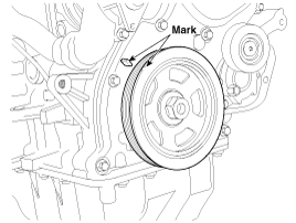
Turn the crankshaft pulley, and align its groove with timing mark "T" of the timing chain cover. (No.1 cylinder compression TDC position)

18.

Remove the crankshaft damper pulley.

(Refer to Timing System - "Crankshaft Damper Pulley")

19.

Remove the A/C compressor.

<a href="content.asp?vehicletype=Passenger&mfrcode=KM&area=KME&langcode=ENG&modelid=JD12&modelyr=2013&mmctype=ac&mmcid=5&group=SHOP&pdftype=&cat1=2013+%3E+G+1%2E6+MPI&firstnodedesc=Heating%2CVentilation%2C+Air+Conditioning&sitinfolist=71%5E7120%5E71200200%5Enone%5E801%5E1%5EENG%5EKM%5EJD12%5E2013%5Eac%5E5%5Enone%5Enone%5Enone%5ESHOP%5E%2471%5E7120%5E71200200%5Enone%5E801%5E8%5EENG%5EKM%5EJD12%5E2013%5Eac%5E5%5Enone%5Enone%5Enone%5ESHOP%5E%2471%5E7120%5E71200200%5Enone%5E801%5E4%5EENG%5EKM%5EJD12%5E2013%5Eac%5E5%5Enone%5Enone%5Enone%5ESHOP%5E%2471%5E7120%5E71200200%5Enone%5E801%5E2%5EENG%5EKM%5EJD12%5E2013%5Eac%5E5%5Enone%5Enone%5Enone%5ESHOP%5E%24" target="_blank">(Refer to Heating, Ventilation Air conditioning -"Compressor")</a>

20.

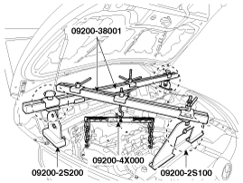
Using the SST (support SST No. : 09200-2S100 or 2S200, beam SST No. : 09200-38001 or 3N000, adapter SST No. : 09200-4X000), hold the engine and transaxle assembly safely.

<a href="content.asp?vehicletype=Passenger&mfrcode=KM&area=KME&langcode=ENG&modelid=JD12&modelyr=2013&mmctype=tr&mmcid=242&group=SHOP&pdftype=&cat1=2013+%3E+D+1%2E6+TCI%2DU2&firstnodedesc=Manual+Transaxle+System&sitinfolist=51%5E5105%5E51050100%5Enone%5E801%5E1%5EENG%5EKM%5EJD12%5E2013%5Etr%5E242%5Enone%5Enone%5Enone%5ESHOP%5E%2451%5E5105%5E51050100%5Enone%5E801%5E8%5EENG%5EKM%5EJD12%5E2013%5Etr%5E242%5Enone%5Enone%5Enone%5ESHOP%5E%24" target="_blank">(Refer to Manual Transaxle System - "Manual Transaxle")</a>

21.

Remove the intercooler inlet hose & pipe.

(Refer to Intake And Exhaust System – “Intercooler Pipe & Hose”)

22.

Remove the roll rod bracket.

(Refer to Engine And Transaxle Assembly - "Engine Mounting")

23.

Remove the oil pan and the oil strainer.

(Refer to Lubrication System - "Oil Pan")

24.

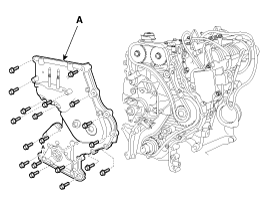
Remove the timing chain cover (A).

note

Remove thoroughly sealant and oil etc left at the sealing surface after remove the chain cover and oil pan. (If any impurities are left at the sealing face, oil may leak after reassembly even with the sealant application.)

Installation
1.

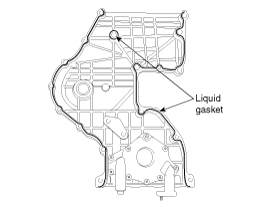
Apply liquid gasket evenly to the mating surface of timing chain cover.

note

Standard liquid gasket : LOCTITE 5900, LOCTITE 5900H, THREE BOND 1217H

Check that the mating surfaces are clean and dry before applying liquid gasket.

Assemble the timing chain cover in 5 minutes after applying the liquid gasket.

Apply liquid gasket in a 3mm wide bead without stopping.

2.

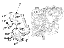
Install the timing chain cover (A).

Tightening torque

Bolt (B, C, F) :

19.6 ~ 26.5N.m (2.0 ~ 2.7kgf.m, 14.5 ~ 19.5lb-ft)

Bolt (D, E) :

9.8 ~ 11.8N.m (1.0 ~ 1.2kgf.m, 7.2 ~ 8.7lb-ft)

Bolt (G) :

42.2 ~ 54.0N.m (4.3 ~ 5.5kgf.m, 31.1 ~ 39.8lb-ft)

3.

Install the front oil seal.

(Refer to Timing System - "Front Oil Seal")

4.

Install the other parts reverse order of removal.

note

Refill engine oil.

Clean the battery posts and cable terminals with sandpaper.

Assemble and then apply grease to prevent corrosion.

Inspect for fuel leakage.

-

After assembling the fuel line, turn on the ignition switch (do not operate the starter) so that the fuel pump runs for approximately two seconds and fuel line pressurizes.

-

Repeat this operation two or three times, then check for fuel leakage at any point in the fuel lines.

Refill radiator and reservoir tank with engine coolant.

Bleed air from the cooling system.

-

Start engine and let it run until it warms up. (Until the radiator fan operates 3 or 4 times.)

-

Turn Off the engine and let it cool down. Check the level in the radiator, add coolant if needed. This will allow trapped air to be removed from the cooling system.

-

Put radiator cap on tightly, then run the engine again and check for leaks.

Яндекс.Метрика