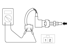
Push the clutch switch in the direction of the arrow to make sure that continuity is cut off.

Condition | Clutch Pedal pressed | Clutch Pedal Released |
Switch Operation | ON (below 1.0Ω ) | OFF ( Infinite Ω ) |
Check clutch switch pull-up voltage
IG KEY "OFF", ENGINE "OFF".
Disconnect clutch switch connector.
IG KEY "ON".
Measure the voltage between signal terminal of clutch switch harness connector and chassis ground.
Specification : 11.5V ~ 13.0V
Check open in clutch switch signal circuit
IG KEY "OFF", ENGINE "OFF".
Disconnect clutch switch connector and ECM connector.
Check continuity between signal terminal of clutch switch harness connector and ECM harness connector.
Specification : Continuity ( below 1.0Ω )
IG KEY "OFF", ENGINE "OFF".
Disconnect clutch switch connector.
Check continuity between clutch switch connector terminal 1 and chassis ground.
Specification : Continuity ( below 1.0Ω )
Remove the clutch switch.
Push the clutch switch in the direction of the arrow to make sure that continuity is cut off.

Condition | Clutch Pedal pressed | Clutch Pedal Released |
Switch Operation | ON (below 1.0Ω ) | OFF ( Infinite Ω ) |
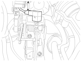
Turn ignition switch OFF and disconnect the negative (-) battery cable.
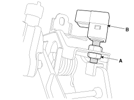
Disconnect clutch switch connector (A).

Remove the clutch switch (B) by loosening a nut (A).

Install in the reverse order of removal.
Adjust the clutch switch.
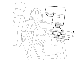
Adjust the gab by rotating the adjust nut (A) to satisfy the standard gap range.
Standard gap range:
0.5 ~ 1.0 mm (0.0197 ~ 0.0394 in.)
Tighten the nut (B) with the specified torque.
Tightening torque:
7.8 ~ 9.8 N (0.8 ~ 1.0 kgf.m, 5.8 ~ 7.2 lb-ft)
