IG KEY "OFF".
Connnect CH A probe to FR signal terminal (Pin No.3) of Alternator connector and CH B probe to COM signal terminal (Pin No.1) of Alternator connector.
Warm up the engine to normal operating temperature.
Measure signal waveform of FR and COM.
Specification : Refer to Signal Waveform & Data
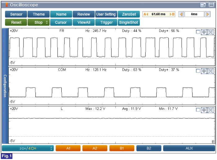
Fig.1) Engine Idle after Warm Up
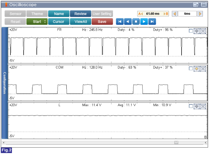
Fig.2) Electrical Load(Engine Idle after Warm Up)
Duty(+) from FR terminal is increased if electrical loads are ON(Head Lamp and Defrost are ON) PCM controls generation of alternator with duty from FR terminal when electrical Loads turn on.
Does the Alternator operate properly? (Check variation)
![]() | ▶ Go to "Verification of Vehicle Repair" procedure. |
![]() | ▶ Carefully re-do this troubleshooting guide steps. ▶ If no problems were found with the circuits or connectors, replace the Alternator and go to "Verification of Vehicle Repair" procedure. |