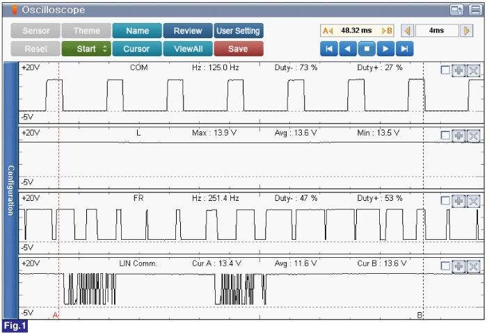
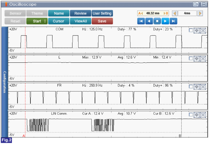
Test Condition : Engine Idle & No Electrical Load and Electrical Load.
Specification : Refer to Figure below


Fig.1) Alternator Signal Waveform at idle and no electrical load.
Fig.2) Alternator Signal Waveform at idle and electrical load.
Ignition switch "OFF"
Connect VMI to GDS and set up an oscilloscope as follow (4-channel);
Channel A (+) : Pin No. 1 (COM) terminal of Alternator.
Channel A (-) : Pin No. 2 (L) terminal of Alternator.
Channel B (+) : Pin No. 3 (FR) terminal of Alternator.
Channel B (-) : Pin No. 1 (LIN Line) terminal of Battery Sensor.
Ignition switch "ON"
Test Condition : Engine Idle & No Electrical Load and Electrical Load.
Specification : Refer to Figure below


Fig.1) Alternator Signal Waveform at idle and no electrical load.
Fig.2) Alternator Signal Waveform at idle and electrical load.
Is the measured value within specification?
 | ▶ Go to "Alternator Inspection" procedure. |
 | ▶ Carefully re-do this troubleshooting guide steps. ▶ If the diagnostics have been performed correctly with no failure found, replace the ECM/PCM and then go to "Verification of Vehicle Repair" procedure. |
When replacing the ECM/PCM, the vehicle equipped with the immobilizer must be performed procedure as below
[In the case of installing used ECM/PCM]
1) Perform "ECM Neutral mode" procedure with GDS. (Refer to "Immobilizer" in BE group)
2) After finishing "ECM Neutral mode", perform "Key teaching" procedure with GDS. (Refer to "Immobilizer" in BE group)
[In the case of installing new ECM/PCM]
Perform "Key teaching" procedure with GDS. (Refer to "Immobilizer" in BE group)
When replacing the ECM/PCM, the vehicle equipped with the smart key system (Button start) must be performed procedure as below.
[In the case of installing used ECM/PCM]
1) Perform "ECM Neutral mode" procedure with GDS. (Refer to "Immobilizer" in BE group)
2) After finishing "ECM Neutral mode", insert the key (or press the start button) and turn it to the IGN ON and OFF position. Then the ECM/PCM learns the smart key information automatically.
[In the case of installing new ECM/PCM]
Insert the key (or press the start button) and turn it to the IGN ON and OFF position. Then the ECM/PCM learns the smart key information automatically.
Ignition switch "OFF"
Refer to "Shop Manual" for following condition:
- Proper tension of alternator drive belt.
- Corrosion, damaged or looseness of battery terminal and alternator terminal.
Ignition switch "ON" & Engine "ON"
Measure the battery voltage via DVOM with GDS.
When batteries are being charged, an explosive gas forms beneath the cover of each cell. Do not smoke near batteries being charged or which have recently been charged. Do not break live circuit at the terminals of batteries being charged.
A spark will occur when the circuit is broken. Keep open flames away from battery.
Is the measured value within specification?
 | ▶ Fault might be intermittent and caused either by poor contact in connectors or wiring harness, or it has been repaired and control module memory is not cleared yet. Thoroughly check terminal of battery, all connectors ( and connections) for looseness, bending, corrosion, contamination, deterioration, and/or damage. ▶ Repair or replace as necessary and then go to "Verification of Vehicle Repair" procedure. |
 | ▶ Carefully re-do this troubleshooting guide steps. ▶ If the diagnostics have been performed correctly with no failure found, replace the alternator and then go to "Verification of Vehicle Repair" procedure. |