System Inspection
■ Sensor Inspection
1.

Visually/physically inspect for the following conditions.

- Vacuum hoses IN engine room for splits, kinks and improper installation.

- Positive crankcase ventilation valve for improper installation, damaged o-rings and malfunctioning.

- Verify that the PCM ground connections are clean and properly tightened.

2.

Check MAPS and ECTS for the following conditions:

- Contamination, deterioration, Poor connection or damaged harness.

- The MAP signal displayed on the GDS should increase AS engine speed increases.

- The engine coolant temperature displayed on the GDS should close to the actual coolant temperature.
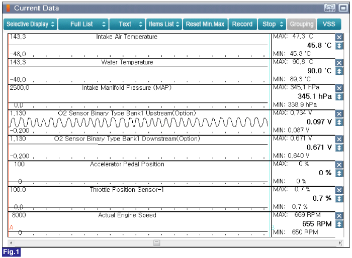
Fig.1) Engine Idle after Warm Up(Engine Sensor Status)

3.

Was a problem found in any of the above areas?

▶ Repair or replace as necessary and go to "Verification of vehicle Repair" procedure.

▶ Go to next step as below.

■ Timing Inspection
4.

IG KEY "OFF".

5.

Connect VMI to GDS and select "Oscilloscope".

6.

Connect Channel A positive probe to Pin No.2 (Signal) and Channel A negative probe to Pin No.1(Ground) on the CKPS connector.

7.

Connect Channel B positive probe to Pin No.2 (Signal) terminal of CMPS harness connector and chassis ground.

8.

Warm up the engine to normal operating temperature.

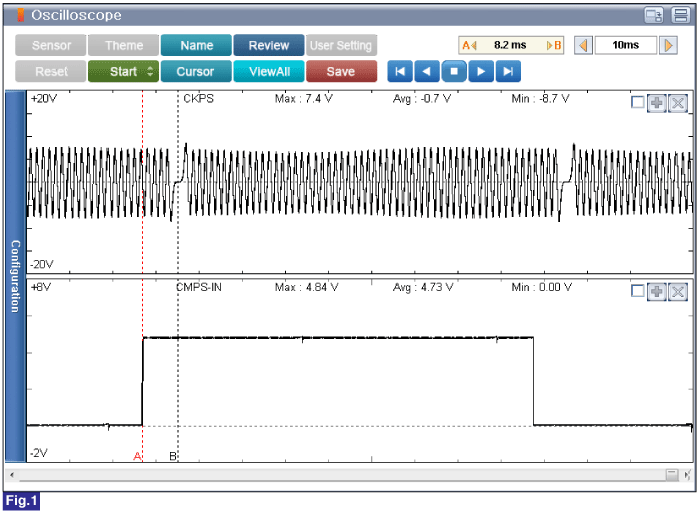
Fig.1) Normal Waveforms of CKPS & CMPS(IN) at Engine idle

A: CKPS & CMPS(Intake side) syncronization - There are about 4~5 teeth between the CKPS missing tooth and CMPS signal

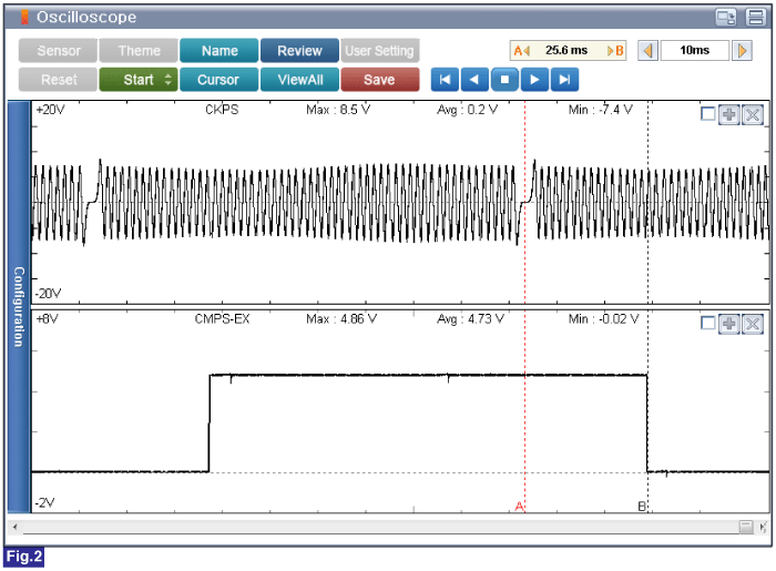
Fig.2) Normal Waveforms of CKPS & CMPS(EX) at Engine idle

A: CKPS & CMPS(Exhaust side) syncronization - There are about 16~17 teeth between the CKPS missing tooth and CMPS signal

9.

Is the signal waveform normal?

▶ Go to next step as below.

▶ Repair or readjust as necessary, check that the crankshaft and camshaft are correctly aligned the matching marks of the pulleys. Repair or readjust as necessary and go to "Verification of Vehicle Repair" procedure.

■ Ignition System Inspection
10.

Spark Plug Cable & Ignition Coil Inspection

(1)

Visually/physically inspect the spark plug cable and ignition coil related to the misfiring cylinder(s) for the following conditions.

- Damage, cracks, carbon and flashover

- Poor connection or damaged harness

- Connected to the incorrect cylinders at the ignition coil and spark plug

(2)

Measure the resistance of the spark plug cable related to the misfiring cylinder(s).

Specification : 5.6kΩ/m ±20%

(3)

Measure the resistance of the primary and secondary ignition coil related to the misfiring cylinder(s).

Condition

Temp.(℉)

Primary ignition coil (Ω)

Secondary ignition coil(㏀)

20

68

0.56~0.68

6~8

(4)

Was a problem found in any of the above areas?

▶ Repair or replace as necessary and go to "Verification of Vehicle Repair" procedure.

▶ Go to next step as below.

11.

Spark plug check

(1)

Remove the spark plugs.

(2)

Visually/physically inspect the following items:

- Damaged insulation, Worn electrodes, Oil or fuel fouled, Loose terminals and cracks.

- Check for plug gap : 0.9 - 1.0 mm (0.035 - 0.039 in.)

- Check if the spark plug for the relevant cylinder is lighter in color than the other plugs.

12.

Have any problems been found?

▶ Repair or replace as necessary and go to "Verification of vehicle Repair" procedure.

▶ Go to "Fuel System Inspection" procedure.

■ Fuel System Inspection
13.

Check the fuel for excessive water, alcohol, or other contaminants. Replace contaminated fuel as necessary.

14.

Install a fuel pressure gage.

15.

Inspect fuel pressure with normal idle status.

Specification : 323 ~ 363kpa (3.3 ~ 3.7kgf/㎠, 46.8 ~ 52.6 psi)

16.

Is fuel pressure within the specified value?

▶ Go to next step as below.

▶ Inspect the suspected area. Refer to table as below. Repair or replace as necessary and go to "Verification of Vehicle Repair" procedure.

Condition

Possible Cause

Suspected Area

Fuel Pressure too low

Clogged fuel filter

Fuel filter

Fuel leak on the fuel-pressure regulator that is assembled on fuel pump

Fuel Pump(Fuel Pressure Regulator)

Fuel Pressure too High

Sticking fuel pressure regulator

Fuel Pump(Fuel Pressure Regulator)

■ Fuel Pressure Hold Inspection
17.

Stop the engine and check for a change in the fuel pressure gauge reading.

Specification : After engine stops, the gauge reading should hold for minimum 5 minutes

18.

Is fuel pressure within the specified value?

▶ Go to next step as below.

▶ Inspect the suspected area. Refer to table as below. Repair or replace as necessary and go to "Verification of Vehicle Repair" procedure.

Condition

Possible Cause

Suspected Area

Fuel pressure drops slowly

Injector leak

Injector

Fuel pressure drops immediately

Stuck open in check valve of the fuel pump

Fuel pump

■ Compression pressure check
19.

Warm up the engine to normal operating temperature.

20.

Remove the fuel pump fuse(15A).

21.

Wait until the engine stopped.

22.

Remove the ignition coils and spark plugs.

23.

Crank the engine to remove any foreign material in the cylinders.

24.

Put a compression pressure gauge into spark plug hole.

25.

Check compression pressure at each cylinder.

Specification : Approx. 1,470kPa (15.0kgf/cm², 213psi)

26.

Is compression pressure for each cylinder displayed within specifications ?

▶ Verify if the engine has excessive coolant consumption. If yes, check for damaged inlet water passage, engine block, cylinder head or head gasket. Repair or replace as necessary and go to "Verification of Vehicle Repair" procedure.

▶ If the cylinder compression in 1 or more cylinders is low, pour a small amount of engine oil into the cylinder through the spark plug hole and repeat compression test for cylinders with low compression pressure.

- If adding oil helps the compression, it is likely that the piston rings and/or cylinder bore are worn or damaged.

- If pressure stays low, a valve may be sticking or seating is improper, or there may be leakage past the gasket. Repair or replace as necessary and go to "Verification of Vehicle Repair" procedure.

Яндекс.Метрика