Component Inspection
■ Glow Plug Resistance Inspection
1.

Ignition switch "OFF"

2.

Disconnect battery (-) cable.

3.

Refer to "Shop Manual" and disconnect GRU connector.

4.

Measure the resistance between Pin No. 6 (Glow Plug) terminal of GRU harness connector and chassis ground.

Specification : Approx. 0.25 - 5Ω (20 ~ 30 °C/68 ~ 86 ℉)

5.

Is the measured value within specification?

▶ Go to "Glow Relay Actuation Test" procedure.

▶ Carefully re-do this troubleshooting guide steps.

▶ If no problems were found with the circuits or connectors, replace the Glow Plug and go to "Verification of Vehicle Repair" procedure.

■ Glow Plug Relay Actuation Test
6.

Ignition switch "OFF"

7.

Connect GDS to Data Link Connector (DLC).

8.

Ignition switch "ON" & Engine "OFF"

9.

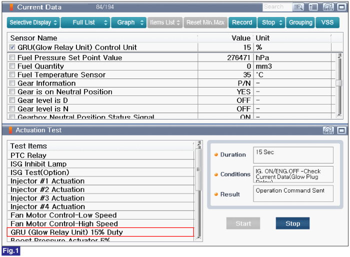
Perform "Glow Relay" in "Actuation Test" with GDS.

10.

Monitor "Glow Relay Unit Control Duty" parameter in "Current Data" with GDS.

Specification : Refer to figure below

Fig.1) Glow relay current data when actuation test is performed.

11.

Is the parameter displayed within specification?

▶ Fault is intermittent caused by poor contact in the sensor’s and/or ECM’s connector or was repaired and ECM memory was not cleared. Thoroughly check connectors for looseness, poor connection, bending, corrosion, contamination, deterioration, or damage. Repair or replace as necessary and go to "Verification of vehicle Repair" procedure.

▶ Carefully re-do this troubleshooting guide steps.

▶ If no problems were found with the circuits or connectors, replace the Glow Plug and go to "Verification of Vehicle Repair" procedure.

Яндекс.Метрика