Is the measured value within specification?
 | ▶ Go to "General Inspection" procedure. |
 | ▶ Refer to "Shop Manual" and re-charge the battery and then go to "Verification of Vehicle Repair" procedure. |
If time after engine "OFF" is not past 20 minutes, to remove remained current, turn the ignition switch to "ON" and turn on the electronic devices (Head lamp, blower motor, rear defogger, etc.).
Turn off the electronic devices and ignition switch.
Measure the voltage between (+) terminal and (-) terminal of battery.
Specification : Approx. 12.5 - 12.9V(20℃/68℉)
Is the measured value within specification?
 | ▶ Go to "General Inspection" procedure. |
 | ▶ Refer to "Shop Manual" and re-charge the battery and then go to "Verification of Vehicle Repair" procedure. |
Battery terminal and fuse
- Loose or corrosion on battery terminal cable.
- Testing continuity of fuse.
Drive belt Inspection
- Inspect for tear and abrasion.
Adjust tension of the belt. (Refer to "Shop Manual")
Alternator noise and wiring harness inspection.
- Inspect for condition of wiring harness of alternator.
- Check for abnormal noise on alternator under engine operation.
Have any problems been found?
 | ▶ Repair as necessary and go to "Verification of Vehicle Repair" procedure. |
 | ▶ Go to "Charging Voltage Inspection" procedure. |
Ignition switch "ON" & Engine "ON"
Turn on the all the electronic devices "ON".
Maintain engine speed at approx. 2,500RPM.
Measure the voltage between (+) terminal and (-) terminal of battery.
Specification : Approx. 13.5 - 14.5V
Is the measured value within specification?
 | ▶ Go to "Current Data Inspection" procedure. |
 | ▶ Carefully re-do this troubleshooting guide steps. ▶ If no problems were found with the circuits or connectors, replace the Alternator and go to "Verification of Vehicle Repair" procedure. |
Ignition switch "OFF"
Connect GDS to Data Link Connector (DLC).
Ignition switch "ON" & Engine "ON"
Monitor "State of Charge" parameters in "Current Data" with GDS.
Specification : Approx. 14.5V
Compare the "Battery Voltage" and "Battery Sensor Voltage(AMS)" parameters.
Inspect charging voltage and displayed parameters.
Have any problem been found?
 | ▶ Carefully re-do this troubleshooting guide steps. ▶ Monitor parameters that has voltage difference compare to alternator charging voltage. ▶ If abnormal "Battery Voltage: parameter is found and no problems were found with the circuits or connectors, replace the ECM and go to "Verification of Vehicle Repair" procedure. ▶ If abnormal "Battery Sensor Voltage(AMS)" parameter is found and no problems were found with the circuits or connectors, replace the Battery sensor or alternator and go to "Verification of Vehicle Repair" procedure. caution
•
After replacing the ECM, the injector specific data (7 digit) of each cylinder MUST be input into ECM with the GDS
•
In the case the vehicle is equipped with immobilizer or smart key, perform "KEY TEACHING" procedure together (Refer to "Immobilizer" or "Smart key system" in BE group) |
 | ▶ Fault is intermittent caused by poor contact in the sensor’s and/or ECM’s connector or was repaired and ECM memory was not cleared. Thoroughly check connectors for looseness, poor connection, bending, corrosion, contamination, deterioration, or damage. Repair or replace as necessary and go to "Verification of vehicle Repair" procedure. |
Ignition Switch "OFF"
Connect GDS to Data Link Connector(DLC).
Ignition Switch "ON" & Engine "OFF"
Perform "Essential Work After Component Replacement" in "Vehicle S/W Management" with GDS.
Select "ECU Change"
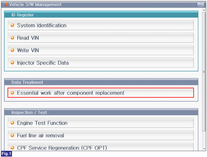
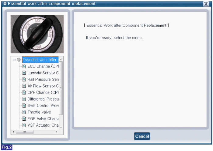
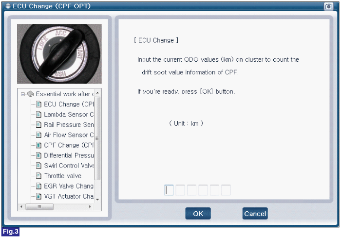
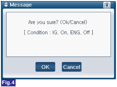
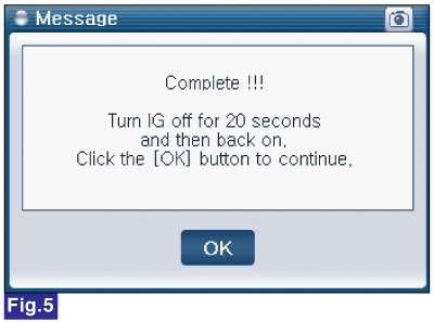
Fig.1) Vehicle S/W Management list of U2 engine
Fig.2) "Essential Work After Component Replacement"
Fig.3) ECU Change
Fig.4) ECU Change confirmation message
Fig.5) Complete