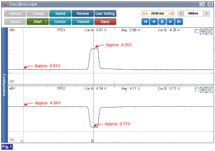
Testing Condition : Idle to Acceleration(W.O.T).
Specification : Refer to Figure below

Fig.1) Normal Throttle Position Sensor Signal waveform at idle to acceleration(W.O.T).
※ Sum of TPS1 and TPS2 signal voltage should equal to approximately 5V.
Ignition switch "OFF"
Connect VMI to GDS and set up an oscilloscope as follow (2-channel);
Channel A (+) : Pin No. 4 (TPS1 Signal) terminal of Throttle Body.
Channel A (-) : Ground
Channel B (+) : Pin No. 5 (TPS2 Signal) terminal of Throttle Body.
Channel B (-) : Ground
Ignition switch "ON" & Engine "ON"
Testing Condition : Idle to Acceleration(W.O.T).
Specification : Refer to Figure below

Fig.1) Normal Throttle Position Sensor Signal waveform at idle to acceleration(W.O.T).
※ Sum of TPS1 and TPS2 signal voltage should equal to approximately 5V.
Is the measured value within specification?
 | ▶ Go to "System Inspection" procedure. |
 | ▶ Carefully re-do this troubleshooting guide steps. ▶ If no problems were found with the circuits or connectors, Throttle Body and then go to "Verification of Vehicle Repair" procedure. |
- Install the component with the specified torques.
- Note that internal damage may occur when the component is dropped or mis- treated.