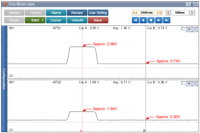
Testing Condition : Accelerator pedal operation.
Specification : Refer to Figure below

Ignition switch "OFF"
Connect VMI to GDS and set up an oscilloscope as follow (2-channel);
Channel A (+) : Pin No. 4 (APS1 Signal) terminal of Accelerator Pedal Position Sensor.
Channel A (-) : Ground
Channel B (+) : Pin No. 6 (APS2 Signal) terminal of Accelerator Pedal Position Sensor.
Channel B (-) : Ground
Ignition switch "ON"
Testing Condition : Accelerator pedal operation.
Specification : Refer to Figure below

Is the measured value within specification?
 | ▶ Carefully re-do this troubleshooting guide steps. ▶ If no problems were found with the circuits or connectors, replace the ECM/PCM and go to "Verification of Vehicle Repair" procedure. caution When replacing the ECM/PCM, the vehicle equipped with the immobilizer must be performed procedure as below.[In the case of installing used ECM/PCM] 1) Perform "ECM Neutral mode" procedure with GDS. (Refer to "Immobilizer" in BE group) 2) After finishing "ECM Neutral mode", perform "Key teaching" procedure with GDS. (Refer to "Immobilizer" in BE group) [In the case of installing new ECM/PCM] Perform "Key teaching" procedure with GDS. (Refer to "Immobilizer" in BE group) caution When replacing the ECM/PCM, the vehicle equipped with the smart key system (Button start) must be performed procedure as below. [In the case of installing used ECM/PCM] 1) Perform "ECM Neutral mode" procedure with GDS. (Refer to "Smart key" in BE group) 2) After finishing "ECM Neutral mode", insert the key (or press the start button) and turn it to the IGN ON and OFF position. Then the ECM/PCM learns the smart key information automatically. [In the case of installing new ECM/PCM] Insert the key (or press the start button) and turn it to the IGN ON and OFF position. Then the ECM/PCM learns the smart key information automatically. |
 | ▶ Carefully re-do this troubleshooting guide steps. ▶ If no problems were found with the circuits or connectors, Acceleration Pedal Position Sensor and then go to "Verification of Vehicle Repair" procedure. |