Has a problem been found?
 | ▶ Repair as necessary and then go to "Verification of Vehicle Repair" procedure. |
 | ▶ Go to "Control Circuit Inspection" procedure. |
Many malfunctions in the electrical system are caused by poor harness and terminals.
Faults can also be caused by interference from other electrical systems, and mechanical or chemical damage.
Thoroughly check all connectors (and connections) for looseness, bending, corrosion, contamination, deterioration, and/or damage.
Has a problem been found?
 | ▶ Repair as necessary and then go to "Verification of Vehicle Repair" procedure. |
 | ▶ Go to "Control Circuit Inspection" procedure. |
Ignition switch "OFF"
Refer to "Shop Manual" and disconnect injector
Is the measured value withing specification?
 | ▶ Go to "Injector Control Low Inspection" procedure. |
 | ▶ Inspect and repair open or short in circuit, and then go to "Verification of Vehicle Repair" procedure. |
Ignition switch "OFF"
Refer to "Shop Manual" and disconnect injector
Is the measured value within specification?
 | ▶ Fault is intermittent caused by poor contact in the sensor’s and/or ECM’s connector or was repaired and ECM memory was not cleared. Thoroughly check connectors for looseness, poor connection, bending, corrosion, contamination, deterioration, or damage. Repair or replace as necessary and go to "Verification of vehicle Repair" procedure. |
 | ▶ Inspect and repair open or short in circuit, and then go to "Verification of Vehicle Repair" procedure. ▶ Carefully re-do this troubleshooting guide steps. ▶ If no problems were found with the circuits or connectors, replace the ECM and go to "Verification of Vehicle Repair" procedure. |
After replacing the ECM, the injector specific data (7 digit) of each cylinder MUST be input into ECM with the GDS
In the case the vehicle is equipped with immobilizer or smart key, perform "KEY TEACHING" procedure together (Refer to "Immobilizer" or "Smart key system" in BE group)
Ignition Switch "OFF"
Connect GDS to Data Link Connector(DLC).
Ignition Switch "ON" & Engine "OFF"
Perform "Essential Work After Component Replacement" in "Vehicle S/W Management" with GDS.
Select "ECU Change"
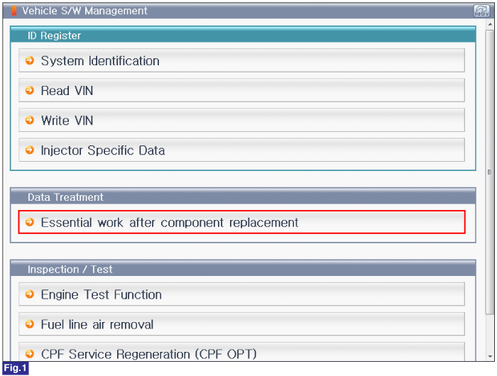
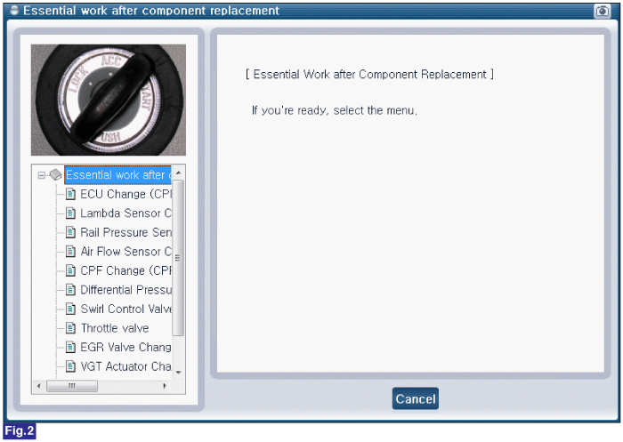
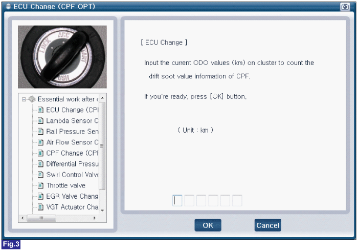
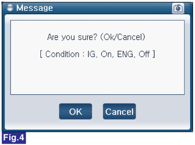
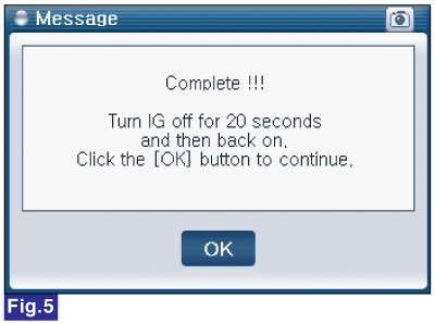
Fig.1) Vehicle S/W Management list of U2 engine
Fig.2) "Essential Work After Component Replacement"
Fig.3) ECU Change
Fig.4) ECU Change confirmation message
Fig.5) Complete