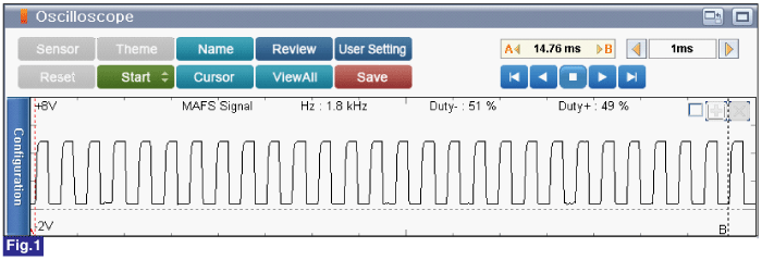
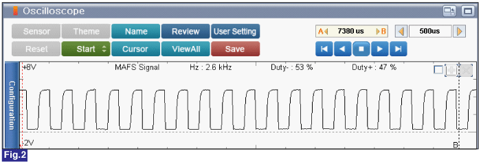
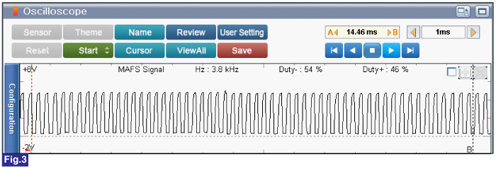
 | ▶ Go to "Intake Air Temperature Sensor 10. Is the measured value within specification?  | ▶ Fault is intermittent caused by poor contact in the sensor’s and/or ECM’s connector or was repaired and ECM memory was not cleared. Thoroughly check connectors for looseness, poor connection, bending, corrosion, contamination, deterioration, or damage. Repair or replace as necessary and go to "Verification of vehicle Repair" procedure. |  | ▶ Carefully re-do this troubleshooting guide steps. ▶ If no problems were found with the circuits or connectors, replace the MAFS and go to "Verification of Vehicle Repair" procedure. |
caution
•
When installing component, tighten it within specification.
•
If component is dropped, check for proper operation. The internal damage may be present. caution
•
Careful not to damage the sensing element. caution
•
When EEGR is replaced, perform "Essential work after component replacement. Otherwise, vehicle performance and emission control may not work properly until auto learning is completed. Vehicle S/W Management ■ In case of MAFS is replaced, perform follwoing procedures; 2. Connect GDS to Data Link Connector (DLC). 3. Ignition switch "ON" & Engine "OFF" 4. Perform "Essential Work After Component Replacement" in "Vehicle S/W Management" with GDS. 5. Select "Air Flow Sensor Change" 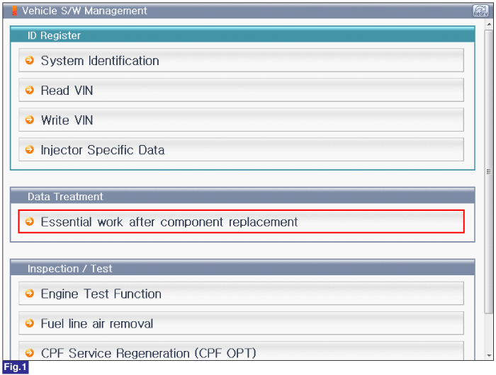 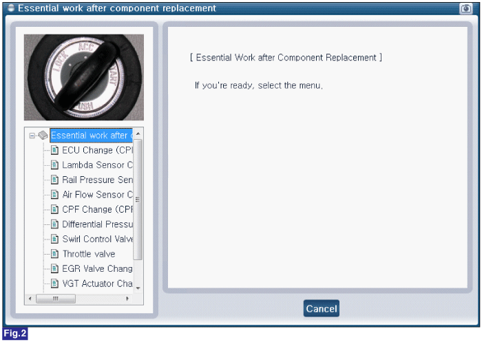 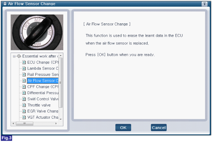  Fig.1) Vehicle S/W Management list of U2 engine Fig.2) "Essential Work After Component Replacement" Fig.3) Air Flow Sensor Change Fig.4) Complete |
