Component Inspection
■ CKPS & CMPS Signal Waveform Inspection
1.

Ignition switch "OFF"

2.

Connect VMI to GDS and set up the Oscilloscope.(2 Channel):

Channel A (+) : Pin No. 2 (CKPS Signal) terminal (CKPS Harness Connector)

Channel A (-) : Ground

Channel B (+) : Pin No. 2 (CMPS Signal) terminal (CMPS Harness Connector)

Channel B (-) : Ground

3.

Ignition switch "ON" % Engine "ON"

4.

Inspection condition : Engine idle

Specification : Refer to figure below

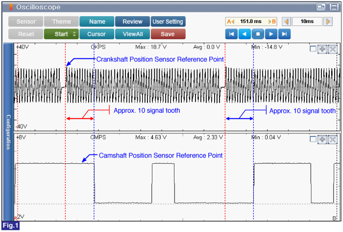
Fig.1) CKPS & CMPS signal waveform under engine idle. ECM determines injection sequence and cylinder based on CKPS and CMPS signals.

When CMPS high signal voltage is decreased to 2.0V, ECM recognizes as low signal. Also, low signal voltage is increased to 3.8V, ECM recognizes as high signal. Low signal of CMPS does not reach 0.0V because of internal resistance of hall sensor.

When low signal of CMPS is over 0.6V, it might be indication of high resistance on CMPS or ground circuit.

5.

Is the measured value within specification?

▶ Fault is intermittent caused by poor contact in the sensor’s and/or ECM’s connector or was repaired and ECM memory was not cleared. Thoroughly check connectors for looseness, poor connection, bending, corrosion, contamination, deterioration, or damage. Repair or replace as necessary and go to "Verification of vehicle Repair" procedure.

▶ Go to "Wiring Inspection" procedure.

caution

When installing component, tighten it within specification.

If component is dropped, check for proper operation. The internal damage may be present.

caution

Apply the engine oil to the O-ring.

Be careful not to damage the O-ring.

caution

Insert the sensor in the installation hole and be careful not to damage when installation.

Be careful not to damage the sensor housing and the connector.

Яндекс.Метрика