3.
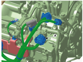
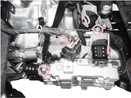
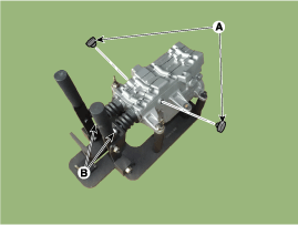
Disconnect the clutch actuator connector (A).
Remove the air cleaner assembly and air duct.
(Refer to Engine Mechnical System - "Air Cleaner")
Remove the battery and battery tray.
(Refer to Engine Electrical System - "Battery")
Disconnect the clutch actuator connector (A).
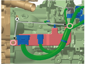
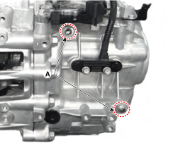
Remove the wiring bracket mounting bolts (A).
Tightening torque :
9.8 ~ 11.8 N.m (1.0 ~ 1.2kgf.m, 7.2 ~ 8.7 lb-ft)
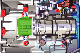
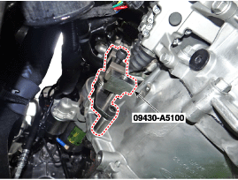
Remove the fork cover (A).
Install the special service tool (09430-A5100).
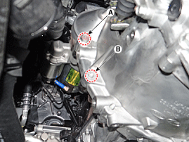
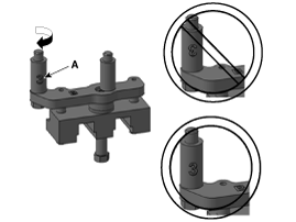
Loosen the starter mounting bolt (A) and the transmission mounting bolt (B).
Tightening torque
(A) : 49.0 ~ 63.7 N.m (5.0 ~ 6.5 kgf.m, 36.2 ~ 47.0 lb-ft)
(B) : 42.2 ~ 53.9 N.m (4.3 ~ 5.5 kgf.m, 31.1 ~ 39.8 lb-ft)
Fix the clutch fork by installing the special service tool (09430-A5100).
How to assemble the SST
Assemble the adapter-B (B) to main body (A).
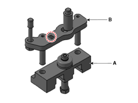
Assemble the space bar-3 (A) to adapter after checking direction of spacer bar.
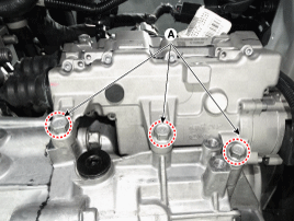
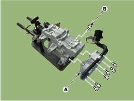
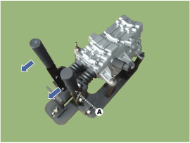
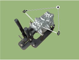
Remove the clutch actuator assembly after loosening the mounting bolts (A: 6 pcs).
Tightening torque :
19.6 ~ 26.5 N.m (2.0 ~ 2.7 kgf.m, 14.5 ~ 19.5 lb-ft)
Remove the clutch actuator.
(Refer to Dual Clutch Transmission Control System - "Clutch Actuator Assembly")
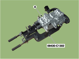
Install the clutch actuator (A) on special service tool (09430-C1302) and fix the actuator using nuts.
Remove clutch actuator motor (A) and ground bolt (B).
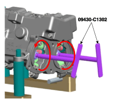
Insert the special service tool (09430-C1302) into ball screw and rotate counter-clockwise until "clicking" sound is heard.
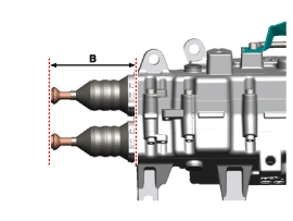
Measure the length (C) from reference plane (A) to the end of rod (B).
Service Standard : 44mm (1.7323in.)
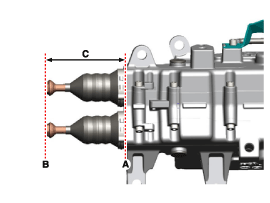
If the length of the pull rod is about 44 mm (1.7323 in.) shorter than specification, replace the dual clutch, clutch actuator, and the engagement bearing.
Install in the reverse order of removal.
Perform the work procedures for abrasion compensation reset before installing the new clutch actuator assembly. (Refer to Clutch Actuator Assembly - "Adjustment")
Check the assembled state of the dowel pins (A) before installing the clutch actuator assembly.
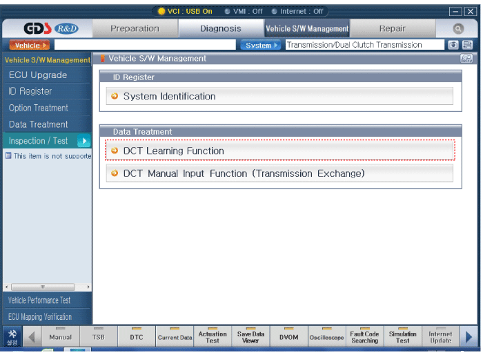
Perform the clutch touch point learning procedure using the GDS after replacing the clutch actuator assembly.
Perform the work procedures for abrasion compensation reset by referring to the table below.
Replacement part | Remedy |
Dual clutch assembly | Initialize |
Clutch actuator assembly | Rewind |
Dual clutch assembly + Clutch actuator assembly | Not required |
Install the faulty clutch actuator (A) on special service tool (09430-C1302) and fix the actuator using nuts.
Remove clutch actuator motor (A) and ground bolt (B).
Insert the special service tool (09430-C1302) into ball screw and rotate counter-clockwise until "clicking" sound is heard.
Measure the length (C) from reference plane (A) to the end of rod (B).
Pull the lever (A) until "click" sound is heard and then measure the length to check for pull rod length of faulty clutch actuator (B).
Remove the clutch actuator from the special service tool (09430-C1302).
Install the new clutch actuator (A) on special tool (09430-C1302) and fix the actuator using nuts.
Remove clutch actuator motor (A) and ground bolt (B).
Insert the special service tool (09430-C1302) into ball screw and rotate counter-clockwise until "clicking" sound is heard.
Fix the pull rod to hook (B) and then remove sealing rubber (A).
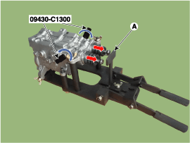
Insert special service tool (09430-C1300) to the sealing rubber hole and then adjust the length of pull rod to the length of previous clutch actuator pull rod by rotating clockwise.
Pull the lever (A) until "click" sound is heard and then measure the length to check for pull rod length (B).
Install the sealing rubber (A).
Install the clutch actuator motor (A) and ground bolt (B) with the O-ring (C).
Tightening torque :
3.9 ~ 5.9 N.m (0.4 ~ 0.6 kgf.m, 2.9 ~ 4.3 lb-ft)
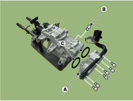
Carefully check and install the O-rings (C).
Install the clutch actuator (A) on special service tool (09430-C1302) and fix the actuator using nuts.
Remove clutch actuator motor (A) and ground bolt (B).
Insert the special service tool (09430-C1302) into ball screw and rotate counter-clockwise until "clicking" sound is heard.
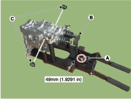
Tighten the nut (A) after setting the T plates (B) to 49 mm (1.9291 in).
Remove the sealing rubber (C).
Insert special service tool (09430-C1300) to the sealing rubber hole and then adjust the pull rod length to the T plates (A) by rotating counter-clockwise.
Fix the pull rod to hook (B) and install the sealing rubber (A).
Pull the lever (A) until "click" sound is heard and then measure the length again to check for specified length (B).
Specified length : 71.5 mm (2.8150 in.)
Install the clutch actuator motor (A) and ground bolt (B) with the O-ring (C).
Tightening torque :
3.9 ~ 5.9 N.m (0.4 ~ 0.6 kgf.m, 2.9 ~ 4.3 lb-ft)
