2.
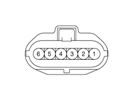
Start engine and check output voltages of APS 1 and 2 at C.T and W.O.T.
Test Condition | Output Voltage (V) [Vref=5V] | |
APS 1 | APS 2 | |
Idle | 0.7 - 0.8 | 0.29 - 0.46 |
Fully depressed | 3.85 - 4.35 | 1.93 - 2.18 |

Connect the GDS on the Diagnosis Link Connector (DLC).
Start engine and check output voltages of APS 1 and 2 at C.T and W.O.T.
Test Condition | Output Voltage (V) [Vref=5V] | |
APS 1 | APS 2 | |
Idle | 0.7 - 0.8 | 0.29 - 0.46 |
Fully depressed | 3.85 - 4.35 | 1.93 - 2.18 |

Turn the ignition switch OFF and disconnect the battery negative (-) terminal.
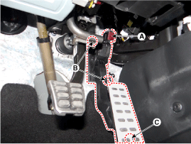
Disconnect the accelerator position sensor connector (A).
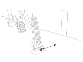
Remove the installation bolt (C) and nuts (B), and then remove the accelerator pedal module.


Install in the reverse order of removal.
Accelerator pedal module mounting nut:
12.7 - 15.7 N.m (1.3 - 1.6 kgf.m, 9.4 - 11.6 lb-ft)
Accelerator pedal module mounting bolt:
8.8 - 13.7 N.m (0.9 - 1.4 kgf.m, 6.5 - 10.1 lb-ft)