Disconnect the injector connector (A).
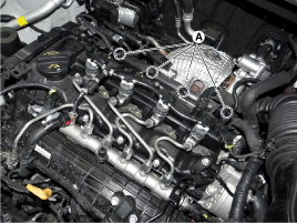
Turn the ignition switch OFF.
Disconnect the injector connector (A).

Measure the resistance between the terminal 1 and the terminal 2.
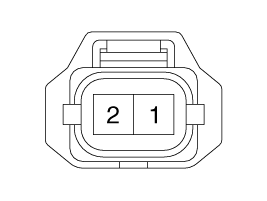
Check if the value is within the specification.
Specification : 0.35 ~ 0.43 Ω [20℃(68℉)]
Turn the igntion switch OFF.
Connect the GDS to Data Link Connector (DLC).
Turn the ignition switch ON.
Select "Vehicle, Model year, Engine, System".
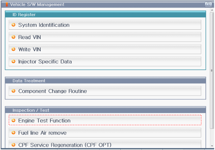
Select "Vehicle S/W Management".
Select "Engine Test Function".
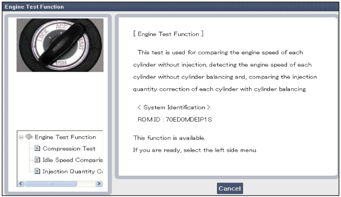
Select "Compression Test".
Perform the test as the message below.
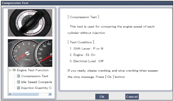
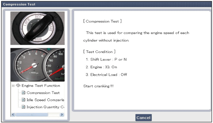
While cranking, the engine is not started.
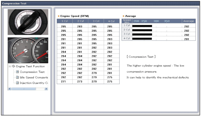
If a cylinder's engine speed is extremly higher or lower than the other cylinders, the cylinder's compression pressure is faulty.
Turn the ignition switch OFF.
Connect the GDS to Data Link Connector (DLC).
Turn the ignition switch ON.
Select "Vehicle, Model year, Engine, System".
Select "Vehicle S/W Management".
Select "Engine Test Function".


Select "Idle Speed Comparision".
Perform the test as the message below.
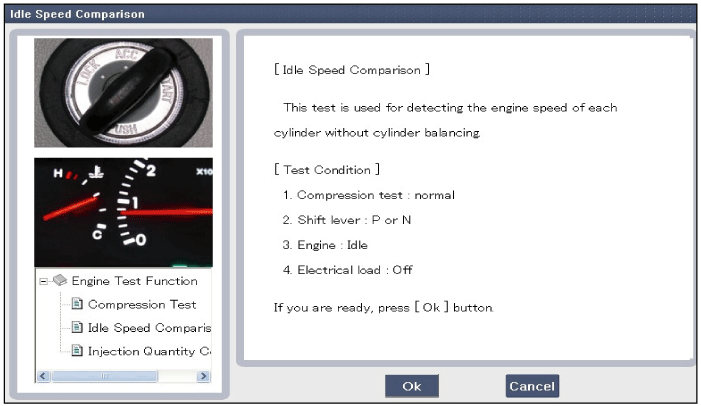
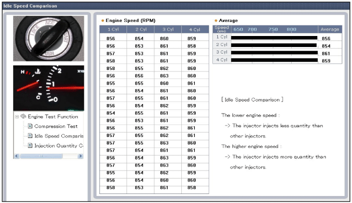
If the injection rate is too much or too less, the idle speed is extremely high or low.
Turn the ignition switch OFF.
Connect the GDS to Data Link Connector (DLC).
Turn the ignition switch ON.
Select "Vehicle, Model year, Engine, System".
Select "Vehicle S/W Management".
Select "Engine Test Function".


Select "Injection Quantity Comparison".
Perform the test as the message below.
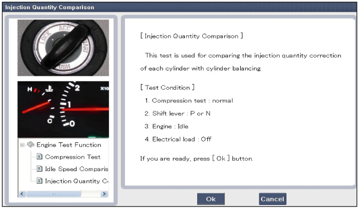
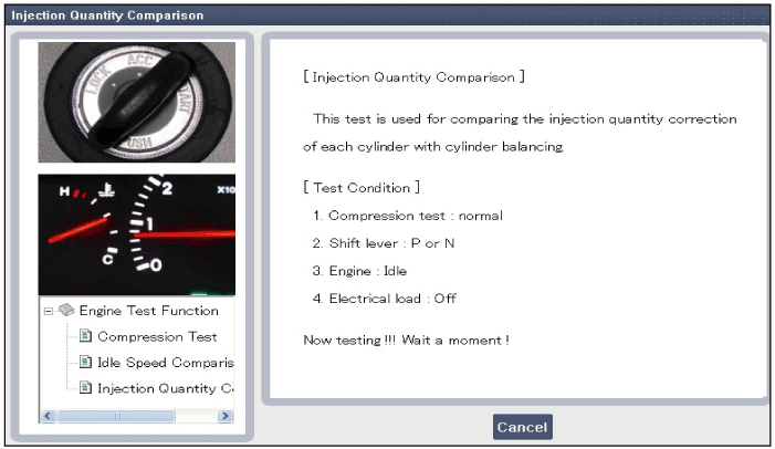
After replacing the faulty injector, check the veicle by performing the tests below.
Compression Test
Idle Speed Comparison
Injection Quantity Comparison
Turn the ignition switch ON.
Connect the GDS to Data Link Connector (DLC).
Turn the ignition switch ON.
Monitor the waveform of each injector.
Analyze the waveform.
Specification : Refer to "Waveform"
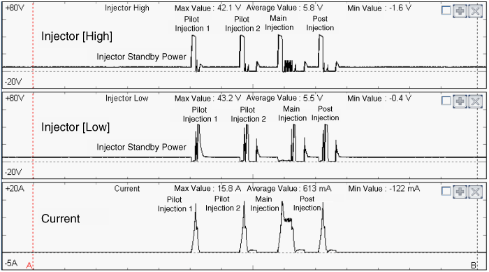
Injector | Injection | Specification | |
Voltage (V) | Current (A) | ||
Injector [High] | Pilot injection 1 | Max. 42 | Max. 16 |
Pilot injection 1 | Max. 42 | Max. 16 | |
Main injection | Max. 42 | Max. 16 | |
Post injection | Max. 42 | Max. 14 | |
Injector [Low] | Pilot injection 1 | Max. 43 | Max. 16 |
Pilot injection 2 | Max. 43 | Max. 16 | |
Main injection | Max. 43 | Max. 16 | |
Post injection | Max. 43 | Max. 14 | |
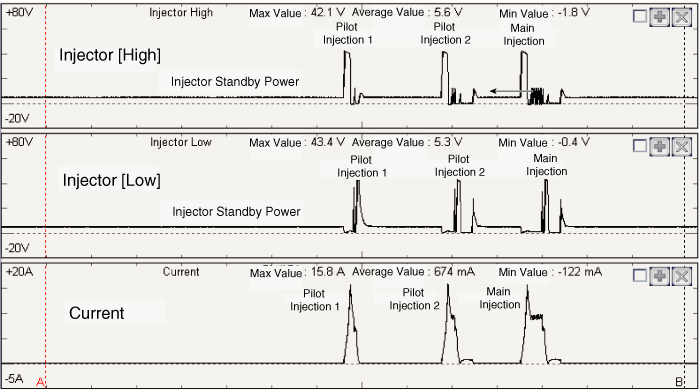
Injector | Injection | Specification | |
Voltage (V) | Current (A) | ||
Injector [High] | Pilot injection 1 | Max. 42 | Max. 16 |
Pilot injection 2 | Max. 42 | Max. 16 | |
Main injection | Max. 42 | Max. 16 | |
Injector [Low] | Pilot injection 1 | Max. 43 | Max. 16 |
Pilot injection 2 | Max. 43 | Max. 16 | |
Main injection | Max. 43 | Max. 16 | |
Common Rail Fuel Injection System operates with extremely high pressure (approximately 2,000bar), so do not perform any work on injection system with engine running or within 30 seconds after the engine stops.
Keep clean the components of common rail system and the working area.
Be careful the influx of foreign substance when installing the fuel supply system.
Remove the protect-cap attaced in the injector, tube or hose etc. to prevent the influx of a foreign substnace just before installing them.
Do not remove injector except for special case.
When installing the injector
- Clean the contact area of the injector and replace the gasket with a new one.
- Vertically insert the injector into the cylinder head to prevent the damage caused by shock.
- Clean the surface under the injector gasket of the cylinder head before installing the injector.
When installing High Pressure Fuel Pipe
- Install the flange nut correctly.
- Do not use again the used high pressure fuel pipe. Always use a new one.
When removing / installing the injector return line
- Insert the connector only in the unlock status.
- Insert the connector with hands. Do not use a tool.
Turn the ignition switch OFF and disconnect the battery negative (-) terminal.
Disconnect the injector connector (A).

Disconnect the injector return line (A).
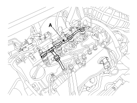
Before connecting or disconnecting the injector return line, always check if the locker is unlocked. Otherwise the plug can be broken and it causes the fuel leak around the injector nipple.
[How to disconnect the injector return line]
Rotate the locker (A) 90˚ counterclockwise.
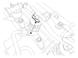
Check if the locker (A) is unlocked.
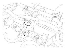
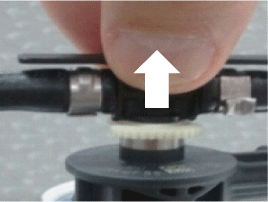
Grap the return line and then separate it from the nipple vertically.
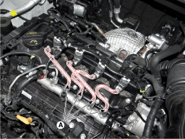
Remove the high pressure fuel pipe (A).
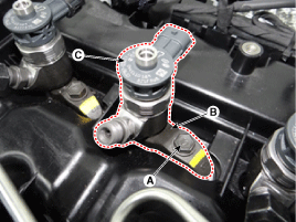
Remove the injector (C) and clamp (B) after loosening the mounting clamp bolt (A).
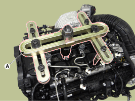
If the injector adheres to the cylinder head, use the special Service Tool (A) [SST No. : 09351-4A300 & 0K338-2F100].
After removing or replacing fuel system below, must perform fuel leakage test procedure. (Refer to "Fuel leak test" in this group.)
Fuel tank
Fuel sender
Fuel filter
High pressure fuel pump
Injector
Common rail
Low pressure fuel line
When installing the injector, MUST REPLACE the O-ring (A) and apply a grease to that.
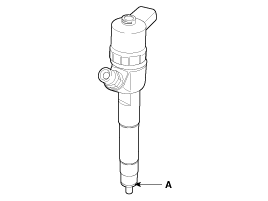
Common Rail Fuel Injection System operates with extremely high pressure (approximately 2,000bar), so do not perform any work on injection system with engine running or within 30 seconds after the engine stops.
Keep clean the components of common rail system and the working area.
Be careful the influx of foreign substance when installing the fuel supply system.
Remove the protect-cap attaced in the injector, tube or hose etc. to prevent the influx of a foreign substnace just before installing them.
Do not remove injector except for special case.
When installing the injector
- Clean the contact area of the injector and replace the gasket with a new one.
- Vertically insert the injector into the cylinder head to prevent the damage caused by shock.
- Clean the surface under the injector gasket of the cylinder head before installing the injector.
When installing High Pressure Fuel Pipe
- Install the flange nut correctly.
- Do not use again the used high pressure fuel pipe. Always use a new one.
When removing / installing the injector return line
- Insert the connector only in the unlock status.
- Insert the connector with hands. Do not use a tool.
Install the injector with specified torque.
If the injector is dropped by mistake, check if there is no problem.
Install the injector on each cylinder.
Install the injector clamp.
Fasten the clamp mounting bolt lightly.
Tighten the flange nuts on both side.
Tighten the injector clamp mounting bolt (A) with specified torque.
Injector clamp mounting bolt :
28.4 ~ 30.4 N.m (2.9 ~ 3.1 kgf.m, 21.0 ~ 22.4 lb-ft)
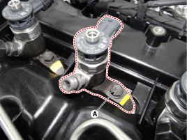
Be sure to use torque wrench.
Tighten the flange nut (A) on the injector side with specified torque.
High pressure fuel pipe flange nut :
24.5 ~ 28.4 N.m (2.5 ~ 2.9 kgf.m, 18.1 ~ 21.0 lb-ft)
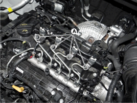
Be sure to use torque wrench.
Tighten the flange nut (A) on the common rail side with specified torque.
High pressure fuel pipe flange nut :
24.5 ~ 28.4 N.m (2.5 ~ 2.9 kgf.m, 18.1 ~ 21.0 lb-ft)
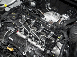
When installing the high pressure fuel pipe, tighten the nut with specified torque using the SST 09314-3A000.
Install the injector return line (A).

Check if the locker (A) is unlocked.

Insert the connector with hands.
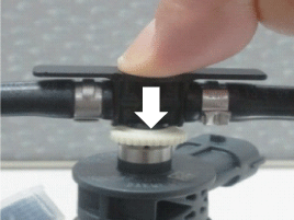
Rotate the locker 90˚ clockwise.
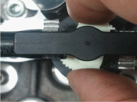
Check if the locker (A) is locked correctly.

Connect the injector connector.
Connect the battery negative (-) terminal.
After replacing injector, MUST input the injector specific data (7 digit) of each cylinder into ECM with scan tool.
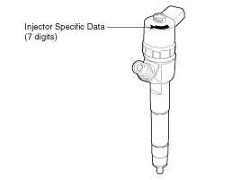
Common Rail Fuel Injection System operates with extremely high pressure (approximately 1,800bar), so never perform any work on injection system with engine running or within 30 seconds after the engine stops.
Keep cleanly the parts and the working area.
Pay attention to a foreign substance.
Just before installing injector, tube or hose, remove the protect-cap attached on them.
Do not remove injector except for special case.
When installing Injector
- Wash the contact area of the injector and replace the gasket with a new one.
- To protect damage caused by shock, vertically insert the injector into the cylinder head.
- Clean the connecting surface of the injector gasket on the cylinder head before installing the injector.
When installing High Pressure Fuel Pipe
- Do not use again the used high pressure fuel pipe.
- Install the flange nut correctly.
After replacing ECM, MUST input the injector specific data (7 digits) of each cylinder into a new ECM with the GDS.
Remove the injector (Refer to "Removal").
Install the injector (Refer to "Installation").
Perform the "Injector Specific Data Input" procedure (Refer to "Injector Specific Data Input").

Turn the ignition switch OFF.
Connect the GDS to Data Link Connector (DLC).
Turn the igntion switch ON.
Select "Vehicle, Model Year, Engine, System".
Select "Vehicle S/W Management".
Select "Component Change Routine".
Perform the injector specific data input procedure as the message below.
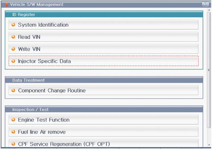
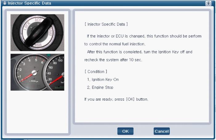
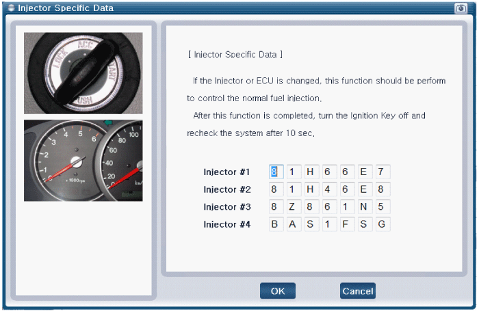
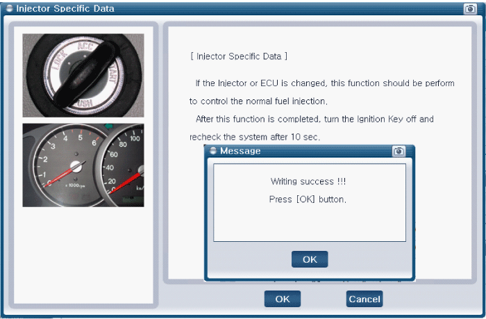
If success message appears, clikc "OK" and then turn the ignition switch OFF.
In about 10 seconds, turn the ignition switch ON and then check the injector specific data memorized in the ECM.
In case of failure, input the injector specific data (7 digits) into ECM again.