Measure resistance between IATS signal terminal and sensor ground terminal.
IATS #1
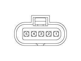
IATS #2
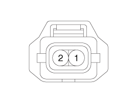
Turn ignition switch OFF.
Disconnect the MAFS (for IATS #1) or BPS (for IATS #2) connector.
Measure resistance between IATS signal terminal and sensor ground terminal.
IATS #1

IATS #2

Check that the resistance is within the specification.
Specification: Refer to Specification section.
Turn the ignition switch OFF and disconnect the battery (-) terminal.
Disconnect the mass air flow sensor connector (A) and the installation clamp (B).
Remove the air intake hose (C) from the mass air flow sensor.
Intake air temperature sensor mounting bolt:
3.9 ~ 5.9 N.m (0.4 ~ 0.6 kgf.m, 2.9 ~ 4.3 lb-ft)
Intake air temperature sensor clamp mounting screw:
2.9 ~ 4.9 N.m (0.3 ~ 0.5 kgf.m, 2.2 ~ 3.6 lb-ft)
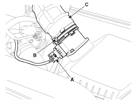
Remove the mass air flow sensor after removing the installation bolts.
Turn the ignition switch OFF and disconnect the battery (-) terminal.
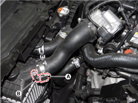
Remove the air duct (A).
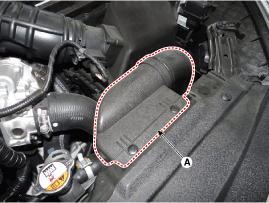
Disconnect the intake air temperature sensor connector (A).
Disconnect the intake air temperature sensor (B) after removing the installation bolt.
Install the component to the specified torques.
Note that internal damage may occur when the component is dropped. In this case, use it after inspecting.
Be careful not to damage the sensing element and the honey cell.
Install the sensor in the reverse order of removal.