12.
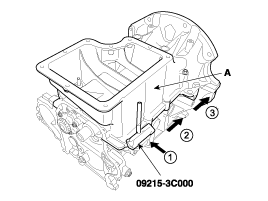
Remove the ladder frame (A).
Insert the blade of SST (09215-3C000) between the cylinder block and the ladder frame. Cut off applied sealer and remove the ladder frame.
Use fender covers to avoid damaging painted surfaces.
To avoid damaging the cylinder head, wait until the engine coolant temperature drops below normal temperature before removing it.
When handling a metal gasket, take care not to fold the gasket or damage the contact surface of the gasket.
To avoid damage, unplug the wiring connectors carefully while holding the connector portion.
Mark all wiring and hoses to avoid misconnection.
Turn the crankshaft pulley so that the No.1 piston is at TDC (Top dead center).
Remove the engine assembly from the vehicle.
(Refer to Engine And Transaxle Assembly - "Engine And Transaxle Assembly”)
Remove the transaxle assembly from the engine assembly.
(Refer to Manual Transaxle System - "Manual Transaxle")
Remove the flywheel.
(Refer to Cylinder Block - "Flywheel")
Install the engine to engine stand for disassembly.
Remove the timing chain.
(Refer to Timing System - "Timing Chain”)
Remove the intake manifold.
(Refer to Intake And Exhaust System - "Intake Manifold")
Remove the exhaust manifold.
(Refer to Intake And Exhaust System - "Exhayst Manifold")
Remove the cylinder head assembly.
(Refer to Cylinder Head Assembly - "Cylinder Head")
Remove the water pipe.
(Refer to Cooling System - "Thermostat")
Remove the water temperature control assembly.
(Refer to Cooling System - "Thermostat")
Remove the oil pan and oil screen.
(Refer to Lubrication System - "Oil Pan")
Remove the ladder frame (A).
Insert the blade of SST (09215-3C000) between the cylinder block and the ladder frame. Cut off applied sealer and remove the ladder frame.
Remove the piston and connecting rod assemblies.
(Refer to Cylinder Block - "Piston and Connecting Rod")
Remove the crankshaft.
(Refer to Cylinder Block - "Crankshaft")
Remove the gasket material.
Using a gasket scraper, remove all the gasket material from the top surface of the cylinder block.
Clean the cylinder block.
Using a soft brush and solvent, thoroughly clean the cylinder block.
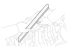
Inspect the top surface of the cylinder block for flatness.
Using a precision straight edge and feeler gauge, measure the surface contacting the cylinder head gasket for warpage.
Flatness of cylinder block gasket surface
Standard : Less than 0.05 mm (0.002 in),
Less than 0.02 mm (0.0008 in) / 100 x 100 (3.937 x 3.937 in)
Inspect the cylinder bore.
Visually check the cylinder for vertical scratchs.
If deep scratchs are present, replace the cylinder block.
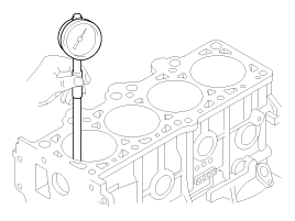
Inspect the cylinder bore diameter.
Using a cylinder bore gauge, measure the cylinder bore diameter at position in the thrust and axial direction.
Standard diameter :
72.00 ~ 72.03 mm (2.8346 ~ 2.8358 in)
Check the cylinder bore size code on the cylinder block.
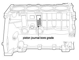
Grade | Size code | Cylinder Bore inner Diameter |
a | A | 72.00 ~ 72.01 mm (2.8346 ~ 2.8350 in) |
b | B | 72.01 ~ 72.02 mm (2.8350 ~ 2.8354 in) |
c | C | 72.02 ~ 72.03 mm (2.8354 ~ 2.8358 in) |
Remove the crankshaft.
(Refer to Cylinder Block - "Crankshaft")
Remove the piston and connecting rod assemblies.
(Refer to Cylinder Block - "Piston and Connecting Rod")
Install the ladder frame (A).
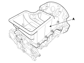
Using a gasket scraper, remove all the old packing material.
Be careful not to damage the contact surfaces.
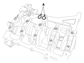
Install the O-ring (A) to cylinder block.
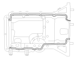
Before assembling the ladder frame, the liquid sealant TB1217H should be applied on ladder frame.
The part must be assembled within 5 minutes after the sealant was applied.
Bead width : 2.5 ~ 3.5 mm (0.1 ~ 0.14 in)
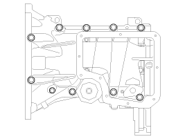
Install and uniformly tighten the ladder frame bolts, in several passes.
Tightening torque :
19.6 ~ 23.5 N.m (2.0 ~ 2.4 kgf.m, 14.5 ~ 17.4 lb-ft)
Assemble the other parts in the reverse order of disassembly.

