13.
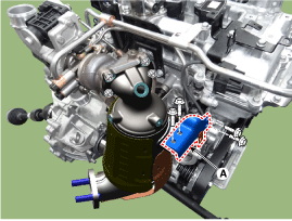
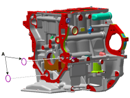
Remove the warm-up catalytic converter (WCC) upper stay (A).
Tightening torque
18.6 ~ 23.5 N.m (1.9 ~ 2.4 kgf.m, 13.7 ~ 17.4 lb-ft)
Remove the engine cover.
(Refer to Engine And Transaxle Assembly - "Engine Cover")
Disconnect the battery negative terminal.
Remove the RH side front wheel.
(Refer to Suspension System - "Wheel")
Remove the engine room under cover and RH side cover.
(Refer to Engine And Transaxle Assembly - "Engine Room Under Cover")
Remove the drive belt.
(Refer to Drive Belt System - "Drive Belt")
Remove the alternator.
(Refer to Engine Electrical System - "Alternator")
Remove the thermostat housing.
(Refer to Cooling System - "Thermostat")
Remove the idler.
(Refer to Drive Belt System - "Idler")
Remove the water pump.
(Refer to Cooling System - "Water Pump")
Remove the crankshaft damper pulley.
(Refer to Drive Belt System - "Crankshaft Damper Pulley")
Remove the cylinder head cover.
(Refer to Cylinder Head Assembly - "Cylinder Head Cover")
Remove the crankshaft position sensor (CKPS).
(Refer to Engine Control / Fuel System - "Crankshaft Position Sensor")
Remove the warm-up catalytic converter (WCC) upper stay (A).
Tightening torque
18.6 ~ 23.5 N.m (1.9 ~ 2.4 kgf.m, 13.7 ~ 17.4 lb-ft)
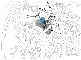
Disconnect the engine ground cable (A) and then remove the engine mounting support bracket (B).
Tightening torque
Ground cable :
10.8 ~ 13.7 N.m (1.1 ~ 1.4 kgf.m, 8.0 ~ 10.1 lb-ft)
Nut (C) :
88.2 ~ 107.8 N.m (9.0 ~ 11.0 kgf.m, 65.1 ~ 79.5 lb-ft)
Bolt (D) and nuts (E) :
58.8 ~ 73.5 N.m (6.0 ~ 7.5 kgf.m, 43.3 ~ 54.2 lb-ft)
Remove the oil level gauge (A).
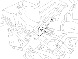
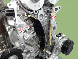
Remove the timing chain cover (A).
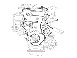
Remove the O-ring (A) from the ladder frame and cylinder bolck.
Install the timing chain cover.
The sealant locations on chain cover and on counter parts (cylinder head, cylinder block) must be free of engine oil and etc.
Before assembling the timing chain cover, the liquid sealant should be applied on the gap between cylinder head and cylinder block.
Assemble the part within 5 minutes of applying sealant.
Bead width : 4.0 mm (0.16 in.)
Apply liquid sealant on timing chain cover. Then, assemble the part within 5 minutes of applying sealant.
Sealant should be applied in a continuous bead in each of the areas indicated below.
Bead width
A : 1.5 ~ 2.5 mm (0.06 ~ 0.10 in.)
B : 2.5 ~ 3.5 mm (0.09 ~ 0.14 in.)
C : 3.0 ~ 4.0 mm (0.12 ~ 0.16 in.)
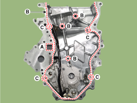
When installing the timing chain, be careful not to remove the applied sealant from the timing cover by contacting with other parts.
The dowel pins on the cylinder block and holes on the timing chain cover should be used as a reference in order to assemble the timing chain cover correctly.
Tightening torque
A :
9.8 ~ 11.8 N.m (1.0 ~ 1.2 kgf.m, 7.2 ~ 8.7 lb-ft) -1EA
B :
18.6 ~ 23.5 N.m (1.9 ~ 2.4 kgf.m, 13.7 ~ 17.4 lb-ft) -12EA
C :
44.1 ~ 53.9 N.m (4.5 ~ 5.5 kgf.m, 32.5 ~ 39.8 lb-ft) -3EA
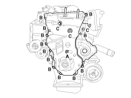
Do not start the engine or perform pressure test within 30 minutes after assembling the timing chain cover.
Install the remaining parts in the reverse order of removal.
