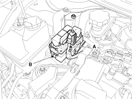
Disconnect the battery positive wiring (A) and then remove the diesel box (B).
Engine removal is not required for this procedure.
Use fender covers to avoid damaging painted surfaces.
To avoid damage, unplug the wiring connectors carefully while holding the connector portion.
Mark all wiring and hoses to avoid misconnection.
Remove the engine cover.
Disconnect the battery negative terminal.
Remove the cylinder head cover.
(Refer to Cylinder Head Assembly - “Cylinder Head Cover”)
Disconnect the battery positive wiring (A) and then remove the diesel box (B).

Remove the under cover.
Remove the RH side front wheel.
Remove the drive belt.
(Refer to Timing System - “Drive Belt”)
Remove the water pump pulley.
(Refer to Cooling System - "Water Pump")
Remove the idler (#1, #2).
(Refer to Timing System - “Idler”)
Remove the drive belt auto tensioner.
(Refer to Timing System - “Drive Belt Tensioner”)
Remove the crankshaft damper pulley.
(Refer to Timing System - “Crankshaft Damper Pulley”)
Remove the A/C compressor.
(Refer to Heating, Ventilation, Air Conditioning - "Compressor")
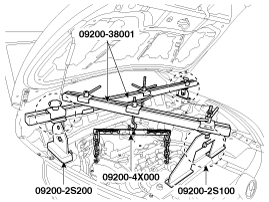
Using the SST (Support SST No. : 09200-2S100 and 2S200, beam SST No. : 09200 - 38001 or 3N000, adapter SST No : 09200 - 4X000), hold the engine and transaxle assembly safely.
Remove the roll rod bracket (A).
Tightening torque
Bolts (B):
49.0 ~ 63.7 N.m (5.0 ~ 6.5 kgf.m, 36.2 ~ 47.0 lb-ft)
Nut (C):
107.9 ~ 127.5 N.m (11.0 ~ 13.0 kgf.m, 79.6 ~ 94.0 lb-ft)

Remove the oil pan and oil strainer.
(Refer to Lubrication System - “Oil Pan”)
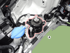
Remove the engine mounting bracket (A).
Tightening torque :
63.7 ~ 83.3 N.m (6.5 ~ 8.5 kgf.m, 47.0 ~ 61.5 lb-ft)
Remove the timing chain cover (A).
[Rotor type oil pump]
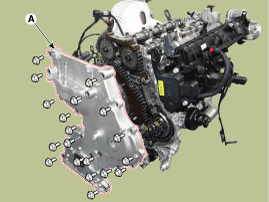
[Vane type oil pump]
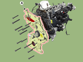
Thoroughly remove sealant and oil residue fom the sealing surface after removing the chain cover and oil pan. (If any impurities are left on the sealing surface, oil may leak after reassembly even with the sealant application.)
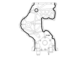
Apply liquid gasket evenly to the mating surface of timing chain cover.
Standard liquid gasket : LOCTITE 5900, LOCTITE 5900H, THREE BOND 1217H
Check that the mating surfaces are clean and dry before applying liquid gasket.
Assemble the timing chain cover in 5 minutes after applying the liquid gasket.
Apply liquid gasket in a 3mm wide bead without discontinuity.
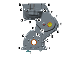
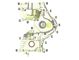
Install the timing chain cover (A).
Tightening torque
Bolt (B, C, F) :
19.6 ~ 26.5 N.m (2.0 ~ 2.7 kgf.m, 14.5 ~ 19.5 lb-ft)
Bolt (D, E) :
9.8 ~ 11.8 N.m (1.0 ~ 1.2 kgf.m, 7.2 ~ 8.7 lb-ft)
Bolt (G) :
42.2 ~ 54.0 N.m (4.3 ~ 5.5 kgf.m, 31.1 ~ 39.8 lb-ft)
[Rotor type oil pump]

[Vane type oil pump]

Install the remaining parts reverse order of removal.