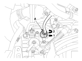
Disconnect the solenoid valve connector (A).
Turn ignition switch OFF.
Remove the air cleaner assembly.
(Refer to Engine Mechanical System - "Air cleaner")
Disconnect the solenoid valve connector (A).

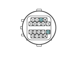
Measure the resistance between power terminal (10) and signal terminal (2).
Specification : 5.1 ± 0.3 Ω
Remove the under cover.
(Refer to Engine Mechanical System - "Engine Room Under Cover")
Remove the drain plug (A) and drain the ATF totally and then reinstall the drain plug.
Tightening torque :
33.3 ~ 43.1 N.m (3.4 ~ 4.4 kgf.m, 24.6 ~ 31.8 lb-ft)
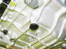
The existing ATF drain plug gasket must be replaced with new one. (Do not reuse it.)
Remove the air cleaner assembly.
(Refer to Engine Mechanical System - "Air Cleaner")
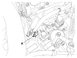
Remove the wiring bracket (A).
Tightening torque :
9.8 ~ 11.8 N.m (1.0 ~ 1.2 kgf.m, 7.2 ~ 8.7 lb-ft)
Remove the air breather hose (A).
Remove the valve body cover (B)
Tightening torque :
11.8 ~ 13.7 N.m (1.2 ~ 1.4 kgf.m, 8.7 ~ 10.1 lb-ft)
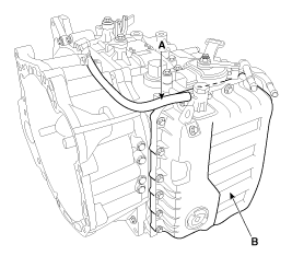
Remove the solenoid valve connector (B) and the oil temperature sensor (A).
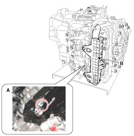
Remove the solenoid valve support bracket (B) and the valve body mounting bolt (A-1ea).
Tightening torque :
9.8 ~ 11.8 N.m (1.0 ~ 1.2 kgf.m, 7.2 ~ 8.7 lb-ft)
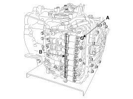
Remove the torque converter control solenoid valve (A).
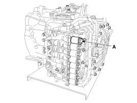
Install in the reverse order of removal.
The existing valve body cover gasket (A) must be replaced with new one. (Do not reuse it.)
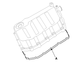
Perform the procedures below after replacing the solenoid valve.
Refill the automatic transaxle with fluid.
(Refer to Hydraulic System - "Fluid")
Reset the automatic transaxle adaptive values using the GDS.
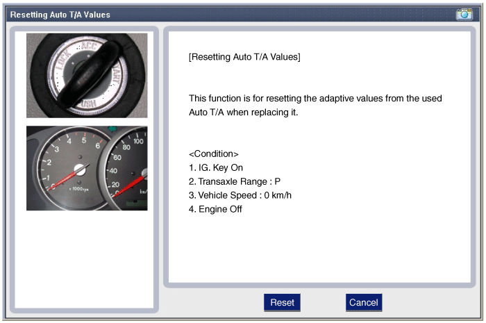
Perform the TCM adaptive values learning procedure.
(Refer to Automatic Transaxle Control System - "Repair procedures")
Confirm that there is no fluid leakage on connections after repairing.