Is the measured value within specification?
 | ▶ Go to "General inspection" procedure. |
 | ▶ Repair as necessary and go to "Verification of Vehicle Repair" procedure. |
IG "OFF".
Measure voltage between battery (-) terminal and (+) terminal.
Specification : Approx. 12.5 ~ 12.9V(20℃)
Is the measured value within specification?
 | ▶ Go to "General inspection" procedure. |
 | ▶ Repair as necessary and go to "Verification of Vehicle Repair" procedure. |
Check battery terminal and fuse.
- Check corrosion and contamination on the battery terminal.
- Check fuse condition.
Check drive belt.
Check alternator condition and wiring condition.
Have any problem been found?
 | ▶ Repair as necessary and go to "Verification of Vehicle Repair" procedure. |
 | ▶ Go to "Check charging voltage" procedure. |
IG "ON" & Engine "ON"
Turn ON all electrical devices.
Raise engine rpm to 2,500RPM.
Measure voltage between battery (-) terminal and (+) terminal.
Specification : Approx. 13.5 ~ 14.5V
Is the measured value within specification?
 | ▶ Go to "Current data monitoring" procedure. |
 | ▶ If no problems were found with the circuits or connectors, Replace the alternator and go to "Verification of Vehicle Repair" procedure. |
Ignition Switch "OFF"
Connect Data Link Connector(DLC) to GDS.
IG "ON" & Engine "ON"
Check "Current Data" with GDS.
Specification : Refer to Fig. below
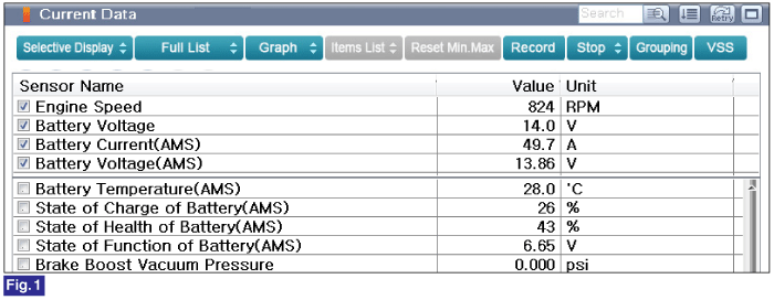
Fig.1 ) At Idle, Current Data of Battery Sensor Voltage and ECU Input Battery Voltage.
Compare "Battery Voltage" to Battery Voltage(AMS)"
Check alternator charging value.
Have any problem been found?
 | ▶ If no problems were found with the circuits or connectors, replace the ECM and go to "Verification of Vehicle Repair" procedure. ▶ If "Battery Voltage(AMS)" has a problem, replace the battery sensor and go to "Verification of Vehicle Repair" procedure. warning
•
After replacing a new ECM, ODO meter and Injector ID No.(7 digits) should be input onto the ECM.
•
If the vehicle has the immobilizer, perform "Key Teaching" of S/W Management and input injector ID No. warning When replacing the ECM, the vehicle equipped with immobilizer or smartkey must be performed the procedure as below. [In the case of installing used ECM] 1. Perform "Neutral mode" procedure with GDS. (Refer to "Immobilizer" in BE group) 2. Insert the key and turn it to the IGN ON and OFF position. Then the ECM key register process is completed automatically. [In the case of installing new ECM] – Insert the key and turn it to the IGN ON and OFF position. Then the ECM key register process is completed automatically. |
 | ▶ Fault is intermittent caused by poor contact in the sensor’s and/or ECM’s connector or was repaired and ECM memory was not cleared. Thoroughly check connectors for looseness, poor connection, bending, corrosion, contamination, deterioration, or damage. Repair or replace as necessary and go to "Verification of vehicle Repair" procedure. |
Ignition Switch "OFF"
Connect GDS to Data Link Connector(DLC).
Ignition Switch "ON" & Engine "OFF"
Perform "Component Change Routine"of "Vehicle S/W Management" with GDS.
Select "ECU Change".
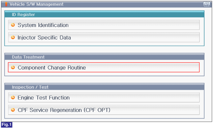
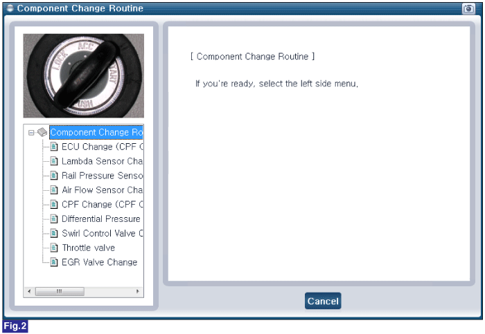
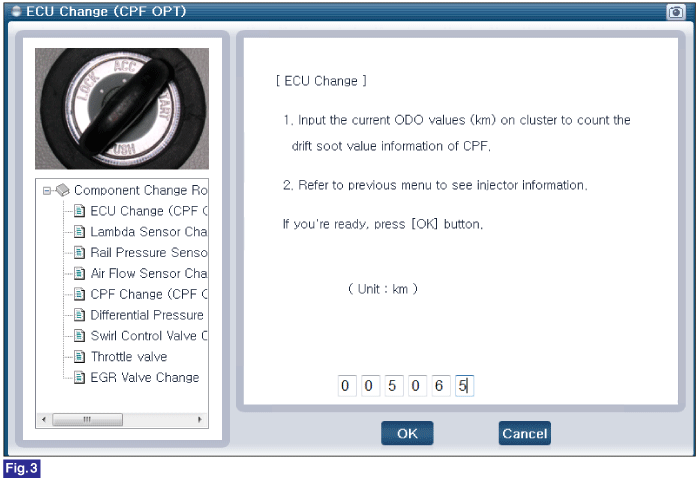
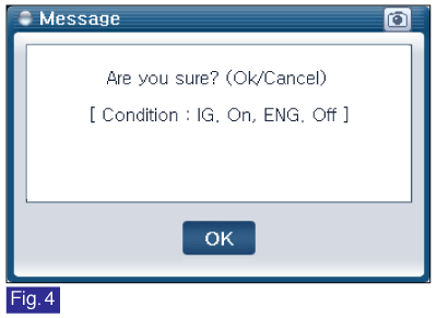
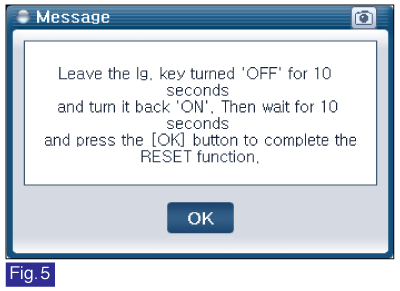
Fig.1 ) S/W Management List of U2 Engine
Fig.2 ) Component Change Routine
Fig.3 ) ECU Change
Fig.4 ) Final Quastion
Fig.5 ) Complete