Is sensor contaminated?
 | ▶ Go to next step as below. |
 | ▶ Replace HO2S(S1) and then go to "Verification of Vehicle Repair" procedure. |
Inspect the front HO2S for any silicon contamination. This contamination will be indicated by a white powdery coating and this will result in a bad false voltage signal.
If contamination is evident on the HO2S, replace contaminated sensor with the new one and go to next step.
Is sensor contaminated?
 | ▶ Go to next step as below. |
 | ▶ Replace HO2S(S1) and then go to "Verification of Vehicle Repair" procedure. |
Warm up the engine to normal operating temperature.
Connect VMI to GDS and select "Oscilloscope".
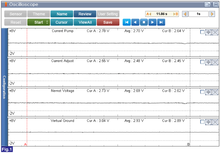
Connect Channel A positive probe to Pin No.6 (Pumping Current) and chassis ground.
Connect Channel A Negative probe to Pin No.4 (Current Adjust) and chassis ground.
Connect Channel B Negative probe to Pin No.1 (Nernst Voltage) and chassis ground.
Connect Channel B Negative probe to Pin No.3 (Virtual Ground) and chassis ground.

Fig.1) Engine Idle after Warm Up
Does the HO2S(S1) operate properly? (Check variation)
 | ▶ Go to "Verification of Vehicle Repair" procedure. |
 | ▶ If no problems were found with the circuits or connectors, Replace the HO2S(S1). |