Ignition Switch "OFF"
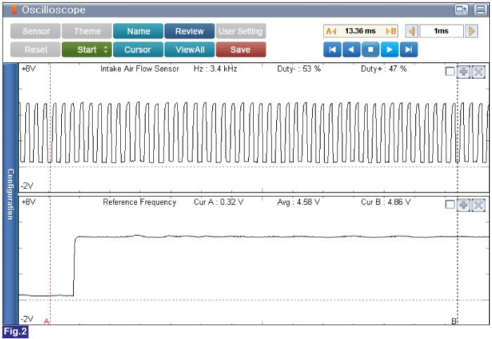
Connect VMI to GDS and perform oscilloscope.(2 Chennel):
Channel A (+) : Pin No.5(Intake Air Flow Sensor Signal) terminal (Intake Air Flow Sensor Connector Side)
Channel A (-) : Ground
Channel B (+) : Pin No.4(Reference Frequency) terminal (Intake Air Flow Sensor Connector Side)
Channel B (-) : Ground
Ignition Switch "ON" & Engine "OFF"
Inspection Condition : Idle & Approx. 1500rpm
Specification : Approx. 2.2kHz (Reference Frequency, Fig. 1) at Idle
Approx. 3.4kHz (Reference Frequency, Fig. 2) at 1500rpm
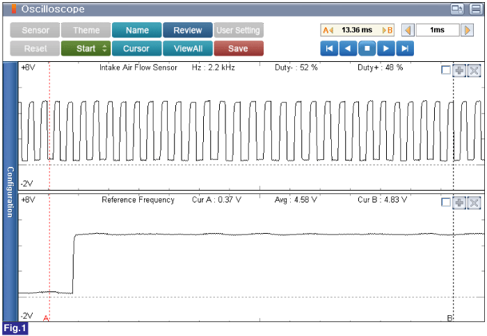
Fig.1 ) Waveform of Intake Air Flow Sensor Signal and Reference Frequency at Idle
Fig.2 ) Waveform of Intake Air Flow Sensor Signal and Reference Frequency at Approx. 1,500RPM
Is the measured value within specification?
![]() | ▶ Fault is intermittent caused by poor contact in the sensor’s and/or ECM’s connector or was repaired and ECM memory was not cleared. Thoroughly check connectors for looseness, poor connection, bending, corrosion, contamination, deterioration, or damage. Repair or replace as necessary and go to "Verification of vehicle Repair" procedure. |
![]() | ▶ If no problems were found with the circuits or connectors, Replace the intake air flow sensor and go to "Verification of Vehicle Repair" procedure. |
When install a part, tighten it within specification.
If drop down the part, check part's operating condition whether it is damaged or not.
Be careful not to damage the sensing element
After replacing mass air flow sensor (MAFS), perform "Component Change Routine". Otherwise, problem that performance or emission concerned can be occured from replacing the part.
Ignition Switch "OFF"
Connect GDS to Data Link Connector(DLC).
Ignition Switch "ON" & Engine "OFF"
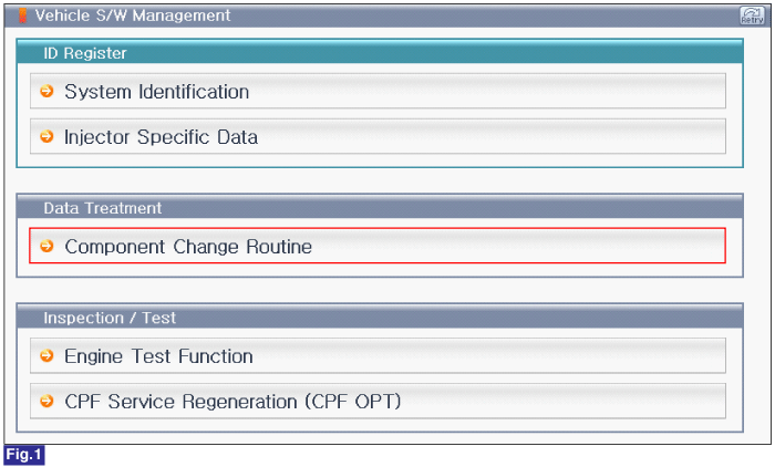
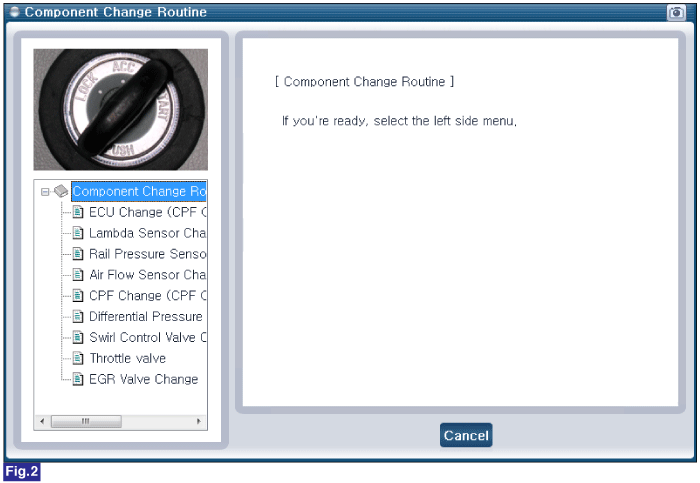
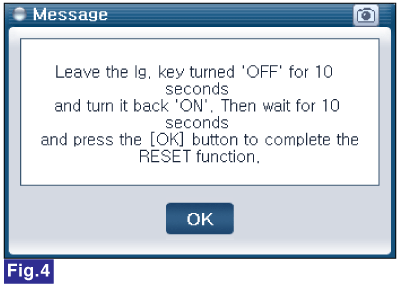
Perform "Component Change Routine"of "Vehicle S/W Management" with GDS.
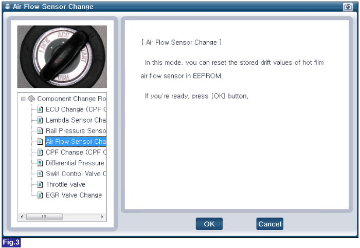
Select "Intake Air Flow(MAF) Sensor Replacement".
Fig.1 ) S/W Management List of U2 Engine
Fig.2 ) Component Change Routine
Fig.3 ) Intake Air Flow(MAF) Sensor Replacement
Fig.4 ) Complete