Ignition Switch "OFF"
Connect VMI to GDS and select oscilloscope.(2 Channel)
Channel A (+) : Pin No. 2(Injector control Low) connector (On Injector Connector)
Channel A (-) : Ground
Channel B (+) : Pin No. 1(Injector control High) connector (On Injector Connector)
Channel B (-) : Ground
Ignition switch "ON" & engine "OFF"
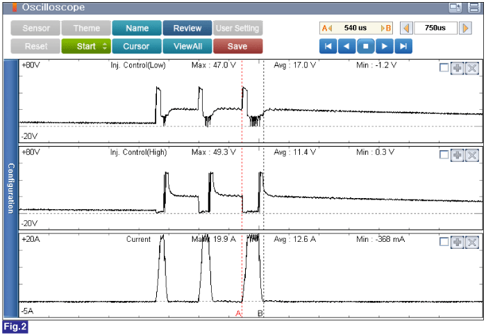
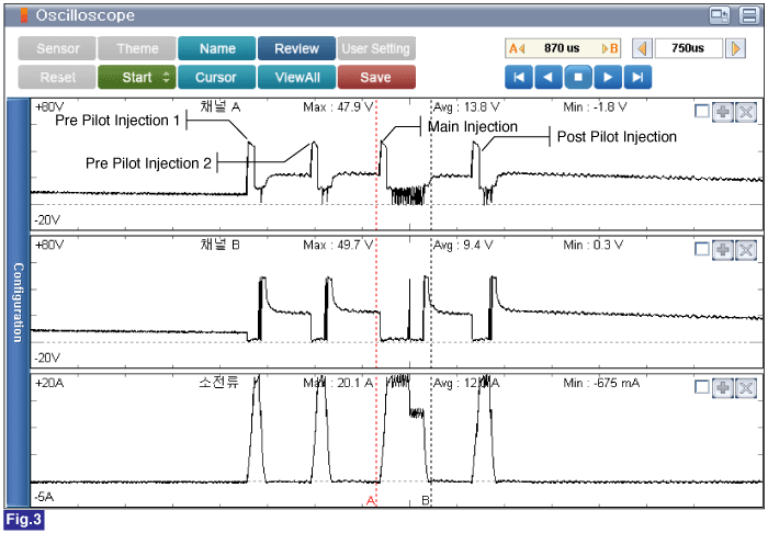
Inspection condition : Engine Idle / 2000rpm / Acceleration
Specification : Refer to Fig. below
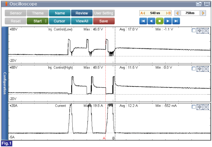
Fig.1 ) Engine Idle, Injector Control Low, High and Current Waveform
Fig.2 ) Approx. 2000rpm, Injector Control Low, High and Current Waveform
Fig.3 ) Acceleration, Injector Control Low, High and Current Waveform
Is the measured value within specification?
![]() | ▶ Fault is intermittent caused by poor contact in the sensor’s and/or ECM’s connector or was repaired and ECM memory was not cleared. Thoroughly check connectors for looseness, poor connection, bending, corrosion, contamination, deterioration, or damage. Repair or replace as necessary and go to "Verification of vehicle Repair" procedure. |
![]() | ▶ Go to "Measure component current" procedure. |
Ignition Switch "OFF"
Disconnect battery (-) cable.
Refer to "Shop Manual" and disconnect the injector connector.
Measure resistance of Pin No. 1(Injector control High) and Pin No. 2(Injector control Low) of the injector connector and chassis ground.
Specification : 0.215 ~ 0.295 kΩ (20℃)
Is the measured value within specification?
![]() | ▶ Fault is intermittent caused by poor contact in the sensor’s and/or ECM’s connector or was repaired and ECM memory was not cleared. Thoroughly check connectors for looseness, poor connection, bending, corrosion, contamination, deterioration, or damage. Repair or replace as necessary and go to "Verification of vehicle Repair" procedure. |
![]() | ▶ If no problems were found with the circuits or connectors, Replace the injector unit and go to "Verification of Vehicle Repair" procedure. |
When install a part, tighten it within specification.
When drop down the part, check part's operating condition whether it is damaged or not.
Common Rail Fuel Injection System operates with extremely high pressure (approximately 1,600bar), so never perform any work on injection system with engine running or within 30 seconds after the engine stops.
Keep cleanly the parts and the working area.
Pay attention to a foreign substance.
Just before installing injector, tube or hose, remove the protect-cap attached on them.
Do not remove injector except for special case.
When installing Injector
- Wash the contact area of the injector and replace the O-ring with a new one.
- Spread oil on the injector O-ring.
- To protect damage caused by shock, vertically insert the injector into the cylinder head.
When installing High Pressure Fuel Pipe
- Do not use again the used high pressure fuel pipe.
- Install the flange nut correctly.
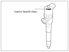
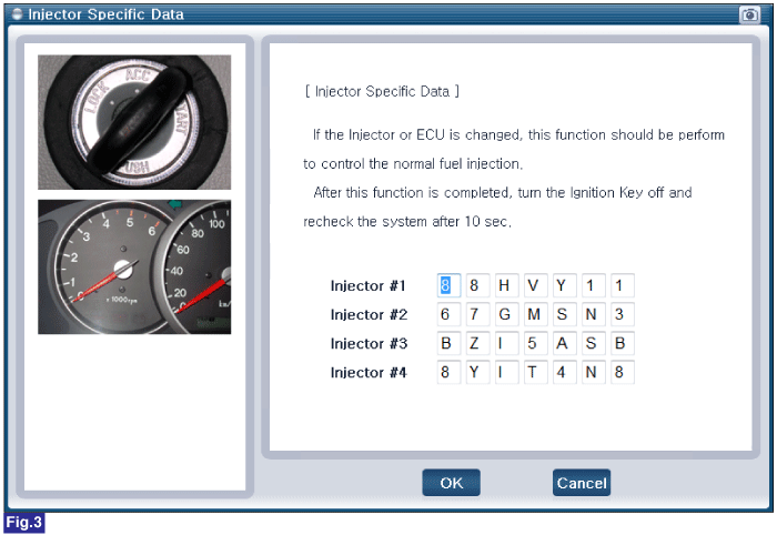
After replacing ECM or injector, input the injector specific data(7 digits) ECM memory.
IG "OFF"
Connect GDS to Data Link Connector (DLC).
Ignition switch "ON" & Engine "OFF"
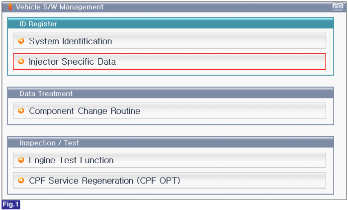
Perform "Injector Specific Data" of "S/W Management" using GDS.
Fig.1 ) S/W Management List of U2 Engine
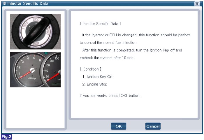
Fig.2 ) Injector Data Register Condition
Fig.3 ) Injector Data Ragigster
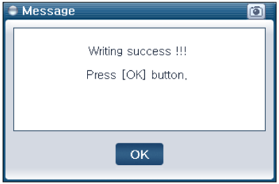
Fig.4 ) Complete