Component Inspection
■ Visual Check(HO2S(S1)
1.

IG "OFF" and disconnect HO2S(S1) connector.

2.

Check that HO2S(S1) is contaminated or damaged by foreign materials.

■ Check HO2S(S1) performance
3.

Warm up the engine to normal operating temperature.

4.

Connect VMI to GDS and select "Oscilloscope".

5.

Connect Channel A positive probe to Pin No.6 (Pumping Current) and Channel A negative probe to Pin No.4 (Trim Resistor).

6.

Connect Channel B positive probe to Pin No.1 (Nernst Voltage) and Channel B negative probe to Pin No.3 (Virtual Ground).
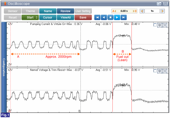
Fig.1) Approx. 2000rpm(A) & Fuel Cut(B)

A : Approx. 2000rpm

CH.1 - Pumping Current & Virtual Ground: - 0.5 ~ 0.4 V

CH.2 - Nernst Voltage & Trim Resistor: -1.0 ~ -0.0 V

B : Fuel Cut

CH.1 - Pumping Current & Virtual Ground: Approx. 0.89V

CH.2 - Nernst Voltage & Trim Resistor: Approx. 0.64V

■ Confirm Part Inspection
7.

Does the HO2S(S1) operate properly? (Check variation)

▶ Go to "Verification of Vehicle Repair" procedure.

▶ Carefully re-do this troubleshooting guide steps.

▶ If problem still occurs, replace HO2S(S1) and then go to "System Inspection" procedure.

Яндекс.Метрика